Directory
1. Principle analysis
2. Comparison of key parameters
3. Design considerations
4. Process flow
5. Quality control
6. Project application differences
7. Failure mode and impact analysis
8. Supply chain and procurement suggestions
9. Conclusion
Refresh rate is one of the most critical performance indicators in LED display technology. It directly impacts motion smoothness, visual comfort, and camera-based shooting quality. In this article, we break refresh rate down from three professional engineering perspectives—structural, electronic, and manufacturing—exploring how it works, how different parameters compare, and how to optimize it from product design to installation and supply-chain management.
The goal: help engineers build LED display systems that deliver high performance, long-term reliability, and stable field operation.
1. How Refresh Rate Works: Structure, Signal Flow & Thermal Logic
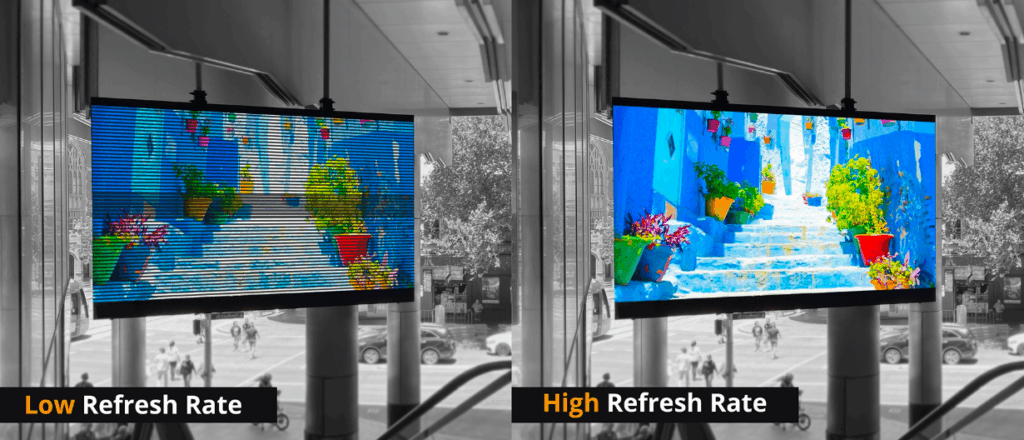
The refresh rate represents how many times per second the LED control system updates the full set of pixels. Conventional LED displays use a scanning-based driver mechanism, where refresh is a timed signal and energy-conversion process orchestrated across all pixels.
Internal Architecture & Signal Chain
Refresh performance relies primarily on LED driver ICs paired with transmission control systems. Most systems use constant-current driver chips and PWM (Pulse Width Modulation) to manage grayscale.
Basic signal chain:
-
Source/processor: Outputs digital video signal
-
Sending card: Processes and packs data, transmits via data cable (Cat5e/Cat6)
-
Receiving card: Decodes data and distributes it to LED modules
-
Driver IC: Handles serial data and brightness output via OE (Output Enable) timing
High-refresh solutions use advanced driver ICs (e.g., MBI5153, ICN2053) designed to reduce internal latency while supporting higher grayscale depth (up to 16-bit, providing 65,536 gray levels). Faster internal latching and OE timing enable visual refresh rates of 1920Hz–3840Hz and higher, with improved low-gray performance.
Thermal Design: Balancing Speed & Heat
Higher refresh rates mean more frequent driver switching events. Although the LED brightness duty cycle remains constant, peak thermal stress and switching losses increase.
Heat-critical components:
-
Driver ICs: Require optimized semiconductor process (CMOS/BiCMOS) plus heat-spreading PCB design (solid copper pours, ground/power planes)
-
LED lamps: Must withstand precise short-pulse currents; material quality affects thermal resistance
Thermal goal:
Keep junction temperature (Tj) within safe operating limits, typically below 125°C.
2. Technical Comparison: Traditional vs. High-Refresh LED Systems
| Parameter | Unit | Traditional System (60Hz–120Hz) | High-Refresh System (≥1920Hz / ≥3840Hz) | Engineering Interpretation |
|---|---|---|---|---|
| Visual Refresh Rate | Hz | 480–960 | ≥1920 (3840 common) | Eliminates visible flicker |
| Frame Rate | Hz | 30–60 | 60/120 | Depends on source, not equal to refresh |
| Grayscale | Bit | 12–14 | 14–16 | Higher depth improves color details |
| Low-Gray Uniformity | – | Poor to average | Excellent | Key for studio & XR filming |
| Scan Frequency | kHz | 50–100 | 100–200 | Higher scan raises refresh rate |
| Power Density | W/m² | 200–350 | 250–400 | Must design thermal margin |
| EMC Risk | – | Low | Higher | Faster clock & signal switching |
3. Engineering Design Considerations

Structural Engineering
-
Flatness tolerance must be within ±0.1mm to avoid visible seams
-
Thermal expansion must be analyzed via FEA, especially for outdoor temperature swings
-
Ventilation paths must follow airflow dynamics to avoid local hot spots
Cooling & Waterproofing
-
Indoor systems: natural convection + chassis dissipation
-
Outdoor systems: sealed IP65/IP66 structures, forced-air cooling or heat pipes
-
Waterproofing: potting compounds, silicone gaskets, staggered or labyrinth-type structural design
Power & Electrical Design
-
N+1 power redundancy
-
Capacity rating: 1.2 to 1.5× peak load
-
Voltage drop must stay below 3%
-
Single-point grounding for EMC stability
4. Manufacturing Process Control
SMT Assembly
-
High-precision pick-and-place (±3µm recommended)
-
Strict reflow temperature profiling to avoid LED damage
-
Low-void, lead-free solder paste for reliable thermal conduction
Module Assembly
-
Torque-controlled fasteners prevent PCB warping
-
For outdoor displays, precise potting to avoid bubbles and moisture gaps
Aging & Stress Testing
-
High-temperature/high-humidity endurance test (48 hours or more)
-
Rapid switching between full-white and full-black to evaluate driver IC stability
5. Quality Control Checkpoints (IQC / IPQC / FQC / OQC)
| Stage | Responsibility | What to Check | Tools |
|---|---|---|---|
| IQC | Electronics / Process | LED wavelength, brightness, IC batch consistency, PCB Tg & impedance | Spectrometer, LCR meter, impedance tester |
| IPQC | Process | SMT precision, solder void rate, reflow profile, potting condition | SMT gauge, X-Ray, hardness tester |
| FQC | Electronics / Mechanical | Refresh rate, grayscale, color uniformity, waterproofing, flatness | Colorimeter, oscilloscope, IP test tools |
| OQC | Packaging / Logistics | Shock protection, labeling accuracy, no transport defects | Vibration tester, environmental chamber |
6. Scenario-Based Application Guidelines
| Scenario | Requirement Priority | Environmental Risks | Key Engineering Focus |
|---|---|---|---|
| Outdoor stadium | High refresh, anti-camera flicker, weatherproof | Sunlight, storms, temperature swings | Redundant power + sealed cooling |
| DOOH billboard | Stability, remote O&M | Salt, dust, lightning | Anti-corrosion coating + surge protection |
| Broadcast & studio | ≥3840Hz, high grayscale, low-brightness uniformity | Precision color calibration | Premium driver ICs + pixel-level calibration |
| Indoor retail | Finesse, thin & lightweight, low EMC | Limited ventilation | Fan-less cooling + EMC control |
7. Failure Modes & Mitigation (FMEA Reference)
| Failure Type | Potential Cause | Severity | Likelihood | Detection | Mitigation |
|---|---|---|---|---|---|
| Low-gray flicker | OE timing error / interference | High | Medium | Medium | High-grade IC, optimized PCB |
| Mass dead LEDs | Reflow temp issues / ESD | Very high | Medium | Medium | Strict reflow profile + full ESD control |
| Visible seams | Poor flatness / thermal expansion | Medium | Medium | High | CNC tolerance + structural lock |
| Local color blocks | Module inconsistency / power imbalance | Medium | Low | Medium | Factory calibration + uniform power |
8. Procurement & Supply-Chain Guidance
LED Lamp Evaluation Criteria
-
Brightness degradation curve
-
Color wavelength binning tolerance
-
UV and temperature resistance
-
Built-in ESD level
Recommended brands: Nichia, Cree, Nationstar, Kinglight
Driver IC Selection Standards
-
Refresh rate ≥ 1920Hz (preferably ≥ 3840Hz)
-
16-bit grayscale processing
-
Built-in low-gray uniformity optimization
-
Good EMC performance
Conclusion
Refresh rate is not just a display specification—it is a multi-disciplinary engineering outcome involving signal processing, thermal design, manufacturing process control, component sourcing, and onsite application matching. Only when all steps are aligned can an LED display deliver true high-performance visuals with stable long-term reliability.
References: