Table of Contents
-
Principles: Internal Structure, Signal Flow, and Thermal Design Logic
-
Key Parameters and Tolerance Control
-
Design Considerations: Structure, Tolerance, Thermal, Waterproofing, Power, and Electrical Safety
-
Manufacturing Process and Quality Control
-
Application Variations and Failure Modes (FMEA)
-
Supply Chain and Procurement Recommendations
-
Conclusion
1. Principles: Internal Structure, Signal Flow, and Thermal Design Logic

The LED display cabinet is the mechanical, electrical, and thermal backbone of a display system. Its design must satisfy modularity, high precision, durability, and long-term reliability.
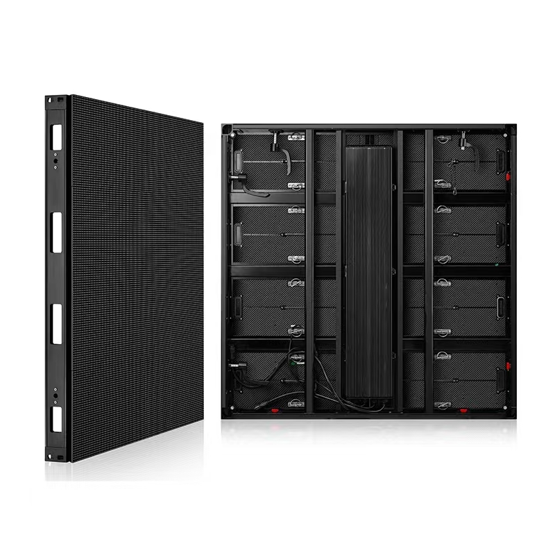
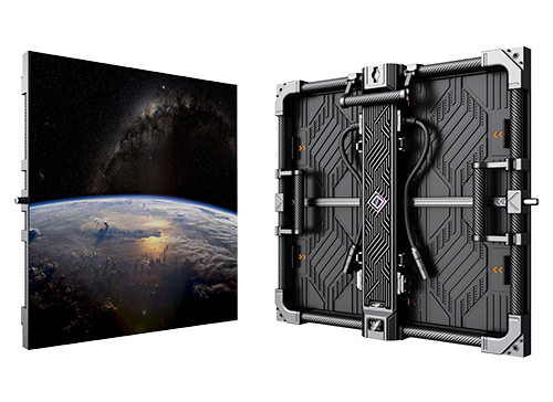
a. Structural Breakdown and Design Logic
Cabinet Materials
Mainstream materials include die-cast aluminum alloy and magnesium alloy.
Die-Cast Aluminum
The optimal choice for rental screens and fine-pixel-pitch indoor displays due to its rigidity, lightweight characteristics, and excellent thermal conductivity. Structural reinforcement ribs must be carefully designed to reduce torsion and long-term deformation.
Extruded Profiles
More cost-effective and commonly used in large traditional outdoor fixed installations.
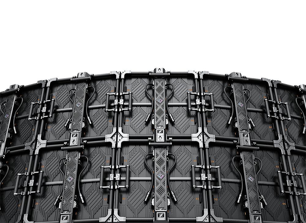
Positioning System
A combination of dowel pins and fast locks:
-
Dowel Pins → Control XY-plane flatness and alignment
-
Fast Locks → Eliminate gaps and ensure rigid mechanical mating
Tolerance Objective:
Cabinet-to-cabinet splicing tolerance must be controlled within ±0.1 mm or even lower to maintain seamless visual alignment.
b. Signal Chain and Power Distribution
Data Transmission
Uses high-speed flat ribbon cables or custom wiring harnesses.
Critical Considerations:
-
Maintain signal integrity (SI) through impedance-matched routing
-
Avoid long parallel signal traces
-
Ensure continuous ground return paths to suppress EMI/RFI
Redundancy
Signal and power ports (typically HUB boards) should support redundancy or loop-through options to enable hot backup.
Power Distribution
-
Low-voltage, high-current systems (5V/12V)
-
Copper busbars or large copper pours are essential to minimize losses:
P=I2RP = I^2R
Voltage Uniformity
Multi-point power injection is recommended to ensure even voltage across the PCB.
c. Thermal Design Logic

LED performance and lifetime are directly tied to junction temperature (Tj). Thermal design is a central factor in system reliability.
Primary Heat Sources:
-
LED chips
-
Driver ICs
Thermal Path
-
LED junction
-
LED package
-
Encapsulation material
-
PCB copper layer
-
Cabinet backplate or baseplate
Conduction + Convection
-
Conduction removes heat from PCB to cabinet
-
Convection removes heat from the cabinet into surrounding air
Key Thermal Elements
Cabinet Backplate
Should have high-density heat-sink fins to maximize surface area.
Die-cast aluminum’s thermal conductivity (150–200 W/m·K) is essential.
Thermal Interface Materials (TIM)
Thermal pads or grease between PCB and cabinet must have extremely low thermal resistance:
Rth<0.5 K/WR_{th} < 0.5\, \text{K/W}
Cooling Systems
-
Fanless design → common for indoor and rental screens
-
Forced-air cooling → used for large high-brightness outdoor screens
2. Key Parameters and Tolerance Control
a. Engineering Parameter Table
| Category | Parameter | Unit | Indoor Fine-Pitch | Rental/Outdoor High Brightness | Standard/Target |
|---|---|---|---|---|---|
| Structural | Splicing Flatness Tolerance | mm | ≤ ±0.05 | ≤ ±0.1 | ISO 2768-m |
| Diagonal Error | mm | ≤ 0.2 | ≤ 0.3 | GD&T | |
| Thermal | Cabinet Temp Rise (ΔT) | K | ≤ 15 | ≤ 25 | Surface temp ≤ 55°C |
| TIM Thermal Resistance | K/W | ≤ 0.4 | ≤ 0.5 | Ultra-low Rth | |
| Electrical | Voltage Ripple | mVp-p | ≤ 50 | ≤ 100 | Avoid IC interference |
| Power Density | W/m² | 300–600 | 600–1000+ | Drives thermal strategy | |
| Protection | IP Rating | — | IP30 | IP65–IP67 | IEC 60529 |
3. Design Considerations: Structure, Tolerance, Thermal, Waterproofing, Power, Electrical
a. Structural & Tolerance Design
Modularity & Maintainability
Fine-pitch displays often use magnetic modules requiring extremely high consistency between:
-
Magnetic force
-
Guiding slots
-
PCB connectors
Tolerance Stack-Up Analysis
Accumulative tolerances from:
Module frame → PCB → Cabinet skeleton → Pins → Locks
must remain below the final target splicing tolerance.
Material Rigidity
Young’s modulus and yield strength must support hanging, stacking, and long-term loads without plastic deformation.
b. Thermal and Waterproofing Design
Outdoor Waterproofing
Sealing system uses:
-
Elastomer gaskets
-
Groove structures
Compression ratio must be precisely calculated:
Too low → leakage
Too high → cabinet deformation & accelerated aging
Breather Valves
A critical component for outdoor displays:
-
Releases humid air and balances pressure
-
Prevents condensation
-
Blocks external water ingress
c. Power & Electrical Safety
EMC/EMI
Shielding:
The cabinet should act as a Faraday cage. Shielded cables are required, with proper grounding.
Filtering:
Power entry requires EMI filters (common-mode and differential-mode chokes).
Grounding:
Single-point grounding + supplemental grounding.
Ground resistance < 4 Ω.
4. Manufacturing Process and Quality Control
a. SMT Key Steps
Solder Paste Printing
Laser-cut stencils with optimized thickness ensure proper solder volume and coplanarity.
Reflow Profile
Must be tuned for LED package temperature limits to prevent:
-
Gold wire oxidation
-
Package deformation
X-Ray Inspection
Necessary for BGA/QFN driver ICs and small-pitch LED packages.
b. Assembly Process
Cabinet Calibration
Before installing modules, empty cabinets must be checked on CMM or precision jigs.
Module Installation
-
Torque-controlled screws to prevent PCB warping
-
Flatness calibration using specialized alignment tools
-
Electrical connection verification for each connector
c. Aging Tests & QC Stages
| QC Stage | Inspection | Tools | Dept |
|---|---|---|---|
| IQC | Die-cast tolerances | CMM, gauges | Structure/QC |
| LED binning | Spectrometers | Electronics | |
| IPQC | SMT checks | X-ray, AOI | Process/QC |
| Torque verification | Torque wrench | Assembly | |
| FQC | White balance, brightness, chromaticity | Color analyzers | Electronics |
| Cabinet splicing accuracy | Alignment tools | Structural | |
| Aging | 48–72h high/low-temp cycles | Test chambers | QC |
| OQC | IP testing | Rain simulation, vacuum tests | QC |
5. Application Variations & Failure Modes (FMEA)
a. Application Variations
| Scenario | Environment | Core Requirements |
|---|---|---|
| Middle East / Desert | High heat, sand | 200%+ thermal margin; IP67; anti-corrosion coating |
| Coastal / High Humidity | Salt mist | Conformal coating; anti-corrosion; IP65 power connectors |
| Stadiums | Vibration, wind load | High rigidity; redundant signal/power; >8000 nits |
| Shopping Malls / XR | Controlled indoor | Fine pitch (<±0.05 mm tolerance); fanless; low light/low noise |
b. FMEA
| Failure Mode | Cause | Effect | Prevention |
|---|---|---|---|
| “Caterpillar” artifacts / bright/dark lines | Impedance mismatch; ground loop break | Distorted image, vertical/horizontal lines | PCB impedance control; shielded cables; high-quality connectors |
| Splicing black/bright lines | Cabinet tolerance out of spec; module stress | Visible seams | Strict die-cast tolerance control; uniform torque; CMM calibration |
| LED pixel dropout | Heat cycling, solder fatigue | Dead pixels | Optimized reflow; strict aging |
| Water ingress | Gasket failure | Short circuits | Correct gasket compression; valve design |
| Color shift | LED binning inconsistency | Patchy colors | Strict LED bin control |
6. Supply Chain & Procurement Recommendations
-
Choose suppliers with CMM-verified die-cast processes
-
Require LED binning reports (color wavelength, brightness)
-
Confirm availability of EMC-certified power supplies
-
Ensure full documentation: BOM, stack-up drawings, tolerance table
-
Verify aging test reports before shipment
7. Conclusion
The LED cabinet is far from a simple mechanical enclosure—it is a tightly integrated structural, electrical, and thermal system. High-precision tolerance control, thermal-path optimization, robust waterproofing, and rigorous quality processes are the foundation of long-term reliability. As pixel pitch continues shrinking and application environments diversify, cabinet engineering becomes even more critical to overall display performance.
References:
ISO 1101 (Geometrical Product Specifications – GD&T)