When spatial designers or audiovisual integrators search for [led cube display] during the architectural planning phase, they are not merely trying to figure out how to hang a screen from the ceiling, but rather how to construct an engineering marvel where physical structure and digital visuals are perfectly integrated.
From an engineering definition perspective, an LED cube display is a multidimensional three-dimensional digital display device with 4 to 6 emitting surfaces. Its core architecture does not lie in the screen itself, but in solving three extreme engineering challenges: first, eliminating edge black frames that disrupt naked-eye 3D visuals through high-precision physical chamfering; second, establishing an efficient thermodynamic heat dissipation model within a fully enclosed polyhedral geometry that does not rely on external airflow; and third, reconstructing pixel coordinates through underlying software to ensure microsecond-level physical frame synchronization across multiple independent video streams.
This guide will provide an in-depth analysis of the underlying hardware architecture and thermodynamic safety standards of LED cube display systems from the objective perspective of frontline R&D engineers.
Eliminating Physical Black Edges: 45° Chamfering Process and Seamless Corner Engineering
When evaluating LED cube displays, the biggest technical pitfall is adopting traditional standard cabinets for “brute-force splicing.” This method inevitably leaves black metal physical frames several millimeters wide at cable junctions and 90-degree corners (i.e., seam fragmentation).
Structural Differences Between Traditional Splicing and True Seamless Cubes
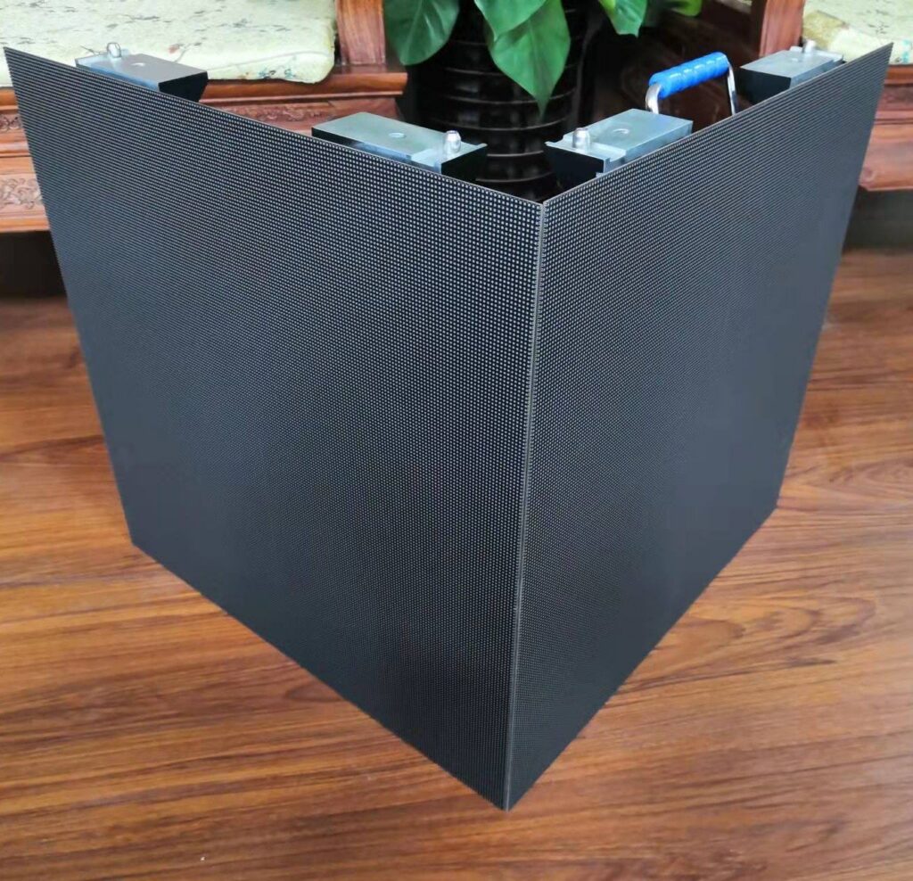
The edges of traditional flat LED cabinets are aligned at 90 degrees. When two such cabinets form a right angle, the thickness of their metal frames overlaps, visually creating a distinct “black line.” For cube displays frequently used to present creative content such as naked-eye 3D liquid overflow or spatial traversal, this black line instantly breaks the three-dimensional illusion.
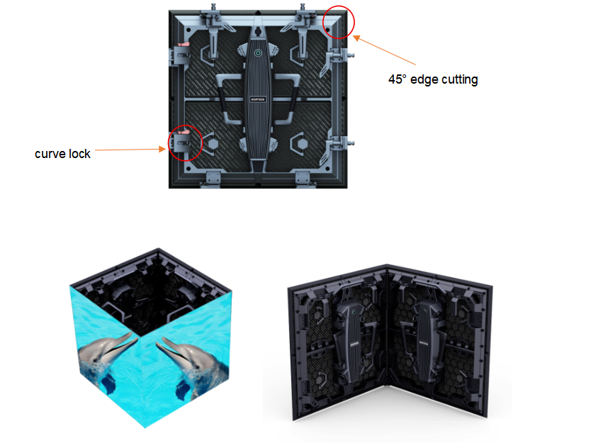
Manufacturing Logic of 45° Chamfered Edges
To achieve an optically “true seamless corner,” the underlying hardware must be structurally redesigned. This requires engineers not only to cut the edges of die-cast aluminum cabinets at 45 degrees, but also to perform extremely precise 45-degree chamfering on the edges of PCB circuit boards densely populated with precision electronic components.
This process heavily relies on expensive five-axis CNC (computer numerical control) precision machining centers. Only by strictly controlling machining tolerances at the micron level can adjacent emitting surfaces fit together with physical seams compressed to within 0.1 mm. At this level of precision, the human eye cannot perceive any physical discontinuity at normal viewing distances.
Technical Trade-off Between Ultra-Fine Pixel Pitch and Edge Protection
Technical example explanation: When designing LED cubes, excessively pursuing ultra-fine pixel pitch (such as below P1.2) is often accompanied by high engineering risks. Because the cube’s corners are protruding 90-degree արտաքին edges, they are highly susceptible to mechanical impacts during transportation, hoisting, or daily operation.
To address the engineering pain point where fine-pitch LEDs at edges are prone to detachment (dead pixels), the industry typically introduces GOB (Glue on Board) technology at cube corner modules. This technology covers the PCB surface and LED pins with a layer of high-polymer transparent epoxy resin, significantly enhancing impact resistance at the corners. This ensures seamless visual performance while meeting the anti-damage physical standards required for equipment in public spaces.
Technical Comparison: Conventional Right-Angle Splicing vs 45° True Seamless Cube
| Engineering Evaluation Dimension | Conventional Right-Angle Splicing Cube | 45° True Seamless Chamfered LED Cube |
|---|---|---|
| PCB Physical Form | Standard rectangle with 90° edges | Precisely chamfered 45° edges |
| Corner Visual Seam | 3–5 mm visible black metal frame | ≤0.1 mm seam, optically continuous |
| 3D Content Performance | Image interrupted at corners | Fully wrapped, supports distortion-free naked-eye 3D parallax |
| Manufacturing Equipment | Achievable with standard machinery | Strong reliance on 5-axis CNC and custom die-casting molds |
Thermal Management and Mechanical Suspension Safety in Fully Enclosed Geometry
Unlike conventional screens mounted on walls or facing outward on one side, typical LED cubes used in malls or exhibitions are fully enclosed structures with 4 sides (ceiling-suspended), 5 sides, or even 6 sides. This enclosed structure introduces highly challenging thermofluid dynamics and mechanical load-bearing issues.
Thermal Dynamics in Enclosed Spaces
When a fully enclosed LED cube is powered on, internal power supplies, receiving cards, and driver ICs generate substantial heat. If heat cannot dissipate, the internal temperature will rapidly rise within tens of minutes, forming a dangerous “oven effect,” leading to severe luminance degradation of LEDs or even motherboard burnout.
In enclosed spaces lacking external air convection, reliance on dust-prone exhaust fans alone is insufficient. Engineering design must adopt “cold and hot aisle physical separation” along with efficient passive heat dissipation architecture. Based on temperature rise test data accumulated from exports to nearly 100 countries (covering extreme heat in the Middle East and extreme cold in Northern Europe), engineers use high thermal conductivity aerospace-grade aluminum profiles to construct the cube’s internal framework. This framework serves not only as a load-bearing structure but also as a thermal conduction bridge, rapidly transferring heat from the enclosed cavity to the large external emitting metal surfaces, where it is dissipated through ambient air.
Structural Stress and Safety Mechanisms in High-Altitude Rigging
In large commercial atriums or stage productions, LED cubes measuring several cubic meters and weighing hundreds of kilograms are often suspended at heights of over ten meters. This installation method allows no margin for engineering error.
From a structural mechanics perspective, it is unacceptable to simply drill holes in the cabinet housing for suspension. A qualified suspended LED cube must include an integrated independent high-strength steel load-bearing frame (Truss Frame) running through the entire structure. All load-bearing points (eye bolts) must be directly welded to the internal steel frame. Additionally, redundant anti-fall steel safety cables must be mandatory. Based on over 10 years of industry experience and more than 6,000 global projects, high-altitude suspension devices must pass static load safety tests at 3 to 5 times the equipment’s own weight before entering the on-site hoisting phase.
Importance of International Safety Certifications in Large Suspended Equipment
Since cube displays are located above densely populated public spaces, their electrical safety compliance is directly related to life and property safety.
Any non-certified custom rigging or electronic equipment poses significant legal and safety risks. Architects must verify whether components comply with stringent international standards such as UL (Underwriters Laboratories) or CE (Conformité Européenne). For example, all internal cables must have high-temperature-resistant insulation sleeves, and external protective masks must meet V-0 flame-retardant standards (self-extinguishing without dripping burning material), fundamentally eliminating the risk of high-altitude electrical fires.
Multi-Face Heterogeneous Pixel Mapping and Signal Synchronization
After overcoming mechanical and thermal challenges, the next critical question is: how to make multiple physical surfaces work in perfect coordination to display seamless, undistorted 3D video? This leads to the crucial domain of control software and pixel mapping engineering.
Coordinate Flattening and Remapping for Multi-Face Video
Traditional video signals (e.g., standard 1920×1080) are based on a single flat two-dimensional X/Y coordinate system. If such signals are directly input into a six-faced LED cube, severe logical discontinuities will occur at the corners.
At the software control layer, the video controller must perform coordinate remapping. The engineering logic is to “unfold” the 3D cube into a two-dimensional layout resembling a “cross” or “T” shape within the virtual canvas of the control software. The controller precisely slices the input high-definition video source based on the actual pixel resolution of each emitting surface. This ensures logical continuity of video pixels when crossing physical seams, such as when a flowing liquid metal visual transitions from the top face to a side face.
Receiving Card Cascading and Multi-Face Frame Synchronization
When displaying high-speed motion content (such as racing cars or rapidly emerging naked-eye 3D elements), even millisecond-level differences in refresh rates across cube faces will result in visible image tearing.
The core solution lies in clock synchronization at the hardware level. Leveraging optimization experience in complex topologies by in-house software and hardware R&D teams, the system’s main controller (sending card) distributes a global synchronized clock signal (Genlock) to all receiving cards across the cube. This physical-level frame synchronization mechanism ensures that even with millions of pixels moving rapidly across multiple surfaces, all frames refresh within the exact same microsecond.
Content Production Guidelines for LED Cubes
The performance limits of hardware systems must be unlocked through proper content formatting. Content production teams must follow specific guidelines:
- 1:1 Resolution Matching: Avoid stretched materials. Designers must construct precise pixel resolutions based on the actual LED count of each emitting surface.
- UV Mapping Expansion: In 3D software such as Cinema 4D or Blender, accurate chamfered models must be built and unfolded via UV mapping before rendering.
- Corner Safe Zones: Critical text information should avoid physical seams at corners, while dynamic visual elements (e.g., particle effects) should deliberately span across corners to enhance naked-eye 3D depth illusion.
Typical Engineering Application Scenarios and Configuration Selection for LED Cubes
Environmental lighting, viewing distance, and mechanical requirements vary drastically across application scenarios. Therefore, hardware configuration must be selected strategically.
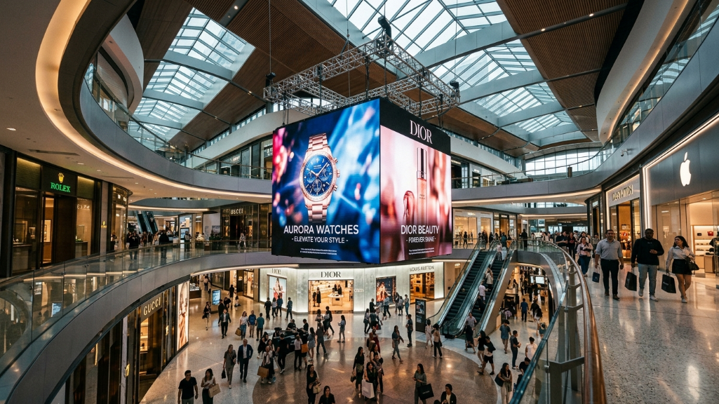
Retail Hanging Cubes in Commercial Atriums
Shopping mall atriums feature abundant natural light or strong indoor illumination.
Selection Focus: Displays must have high brightness (typically ≥1500 nits) to counter ambient light interference. To reduce ceiling load, lightweight cabinet structures made of magnesium alloy or ultra-thin aluminum profiles should be prioritized.
Exhibition Ground-Based Cubes
In such scenarios, cubes are placed on the ground as central interactive displays.
Selection Focus: Bottom emitting surfaces or load-bearing structures must withstand high static pressure (e.g., exhibits placed on top or foot traffic). Due to tight installation schedules, cabinets should include high-strength fast-lock systems to shorten assembly time.
Stage Kinetic Cubes
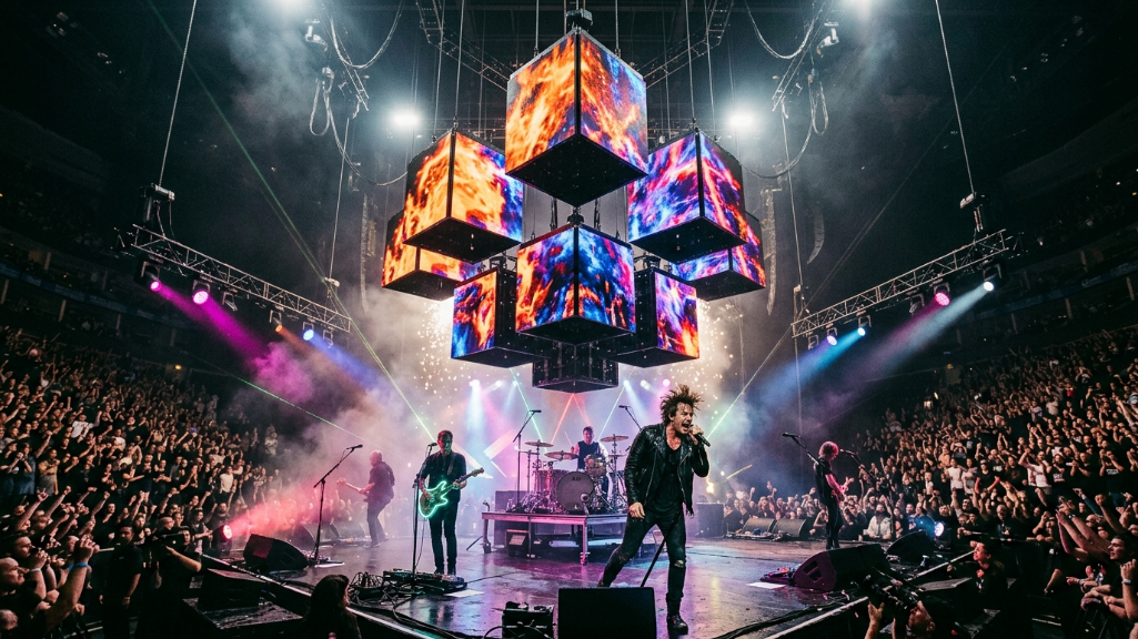
These cubes integrate with DMX winches for dynamic lifting effects during live performances.
Selection Focus: In addition to ultra-high refresh rates (≥3840Hz) for camera capture, internal cable durability against tension and stability of power/signal transmission during motion are critical to preventing black screen failures.
LED Cube Configuration Selection Table for Different Scenarios
| Application Scenario | Core Engineering Challenge | Recommended Configuration & Protection Focus |
|---|---|---|
| Mall Suspension | High-altitude load, strong light interference | Lightweight Mg-Al alloy, ≥1500 nits brightness, dual anti-fall steel cables |
| Exhibition Ground | Frequent assembly/disassembly, physical impact | Fast-lock structure, reinforced bottom steel frame, GOB surface protection |
| Stage Kinetic | Cable fatigue from motion, signal interruption | High-flex tensile aviation cables, DMX control, ≥3840Hz refresh rate |
Core FAQ: Solving Integrator Planning Challenges
Based on common technical blind spots during early project consultations, the following are professional engineering answers for system integrators and architects:
Q1: Can an LED cube display be made into a rectangular prism (with unequal side dimensions)?
Structurally, this is entirely feasible. By customizing aluminum frames with different length ratios and non-standard PCB boards, rectangular prism designs such as 1m × 2m × 1m can be achieved. However, at the software level, content teams must generate video sources with asymmetric resolutions for different sides and perform complex non-uniform pixel mapping.
Q2: If a power supply inside a cube suspended 10 meters high in a mall fails, how is maintenance performed?
A qualified engineering design must never require lowering the entire unit for maintenance. The system should support full front maintenance (100% Front Service). Engineers can use specialized vacuum or magnetic tools to remove any front module directly, exposing internal power supplies and mainboards for quick hot-swappable replacement at height.
Q3: Why are 4-sided or 5-sided cubes generally not suitable for ultra-fine pixel pitches below P1.0 (Micro LED)?
Micro-pitch LEDs are extremely fragile. During 45-degree edge cutting, the physical distance between the cut surface and LED chips is less than 0.5 mm. Under current manufacturing limits, LEDs below P1.0 experience exponentially higher failure rates due to CNC vibration and assembly stress. Therefore, P1.5 to P2.5 remains the optimal balance between visual clarity and mechanical yield.
References:
A Review of Passive Thermal Management of LED Module – Delft University of Technology
Keeping Professional Displays in Sync – Society for Information Display