Table of Contents
Core Definitions & Price Range
Why Do Your Quotes Vary So Much?
LED Packaging: The $200 Line Between Gold Wire and Copper Wire
Driver IC & Refresh Rate: It’s About More Than Image Quality
Cabinet Structure & Heat Dissipation: Real-World Ares Series Case
Scenario-Based Selection: Do You Actually Need P3?
Industry “Hidden Rules”: The Three Traps Behind Cheap P3
ROI: Why Paying $200 More Actually Saves Money
FAQ
Inside Sostron
Conclusion & Call to Action
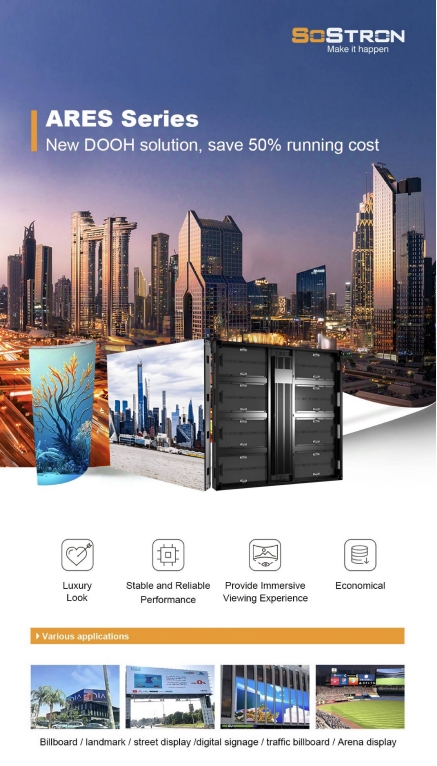
Core Definition & Price Range
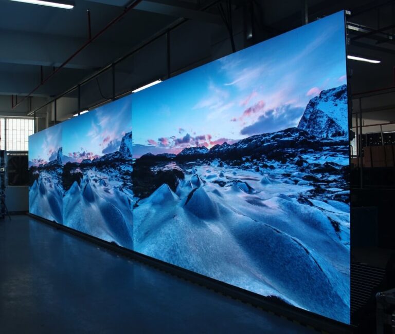
For outdoor P3 LED displays, the common market reference price typically falls between $900 and $2,200 per square meter.
This huge $1,400 price spread often confuses buyers—even experienced ones.
Why Do Your Quotes Vary So Much?
Over the past 20 years, I’ve seen countless clients bring me a $800/sqm P3 quote and ask:
“Why is Sostron more expensive?”
The answer is simple: it’s not only about configuration—it’s about how much hidden risk the manufacturer is willing to gamble with.
Outdoor P3 is nothing like P10.
With 111,111 pixels per sqm, P3 generates significantly more heat and has far more potential failure points. Low-cost manufacturers cut corners where customers can’t see—PCB layers, wire materials, waterproofing, adhesives, and more.

Below are the three core factors that actually determine the price:
LED Packaging (The Lamp): The $200 Line Between Gold Wire and Copper Wire
This is the most overlooked “black box” in B2B sourcing.
Premium Configuration (Sostron Standard)
-
Uses Nationstar SMD1921 or high-end custom gold-wire LEDs.
-
Gold has excellent ductility and oxidation resistance.
-
In hot, humid outdoor environments, gold-wire LEDs maintain stable performance for 5+ years.
Low-Cost Trap
-
In screens under $900/sqm, 90% use copper wire or alloy wire LEDs.
-
Copper oxidizes quickly—especially in rainy or coastal climates.
Consequences
-
No difference in first 3 months.
-
After the first rainy season:
-
Dead pixels
-
“Caterpillar effect” (streaking failure)
-
Cost Gap
Gold wire vs. copper wire alone creates a $150–$200/sqm difference in BOM cost.
2. Driver IC & Refresh Rate: More Than Just Image Quality
Basic ICs (MBI5124 or similar)
-
1920Hz refresh rate
-
OK for long-distance text screens
-
Poor grayscale for P3; produces grainy video playback
Advanced PWM ICs (MBI5153 / ICN2153)
-
3840Hz+ refresh rate
-
Standard for Sostron Ares Series
-
Eliminates moiré when recording on phones
-
Dynamic power-saving reduces surface temperature by 5–8°C
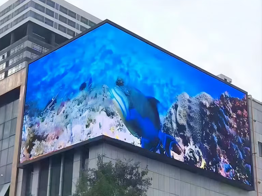
3. Cabinet Structure & Heat Dissipation: Ares in Real Projects
Heat is the biggest enemy of outdoor P3. Poor heat dissipation accelerates brightness decay by 30%.
Case Study: South France Outdoor Project
Client originally wanted iron cabinets to save cost.
But due to the region’s intense summer sunlight, we insisted on the Ares die-cast aluminum cabinet.
Results
-
Lower surface temperature by 10°C compared to iron competitors
-
Thanks to aluminum thermal conductivity + Sostron’s 4-layer PCB gold deposition
-
Achieved 10,000 nits brightness—clear even under direct sunlight
Expert Advice
If wall-mounted with no rear maintenance access:
Die-cast aluminum is your only reliable option—strong heat handling + IP65 protection.
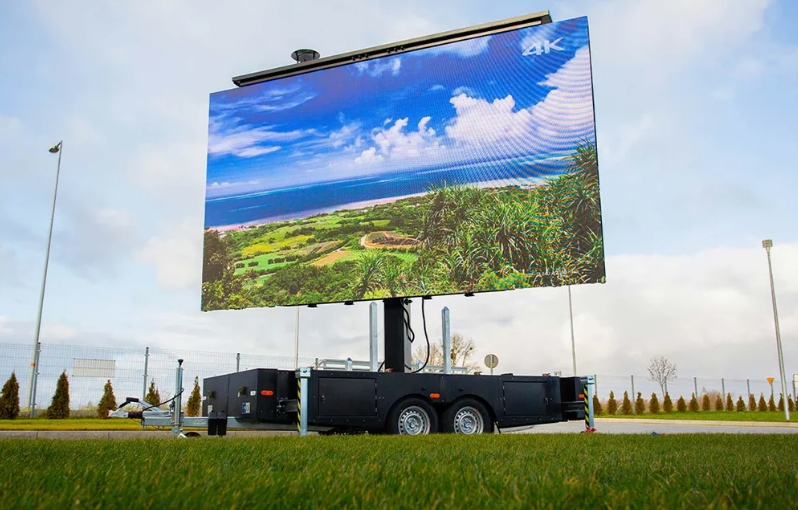
Scenario-Based Selection: Do You Actually Need P3?
Many buyers mistakenly assume “smaller pitch = better.”
Wrong.
Pitch selection is about a balance between viewing distance and budget.
Examples:
-
If your screen is 20 meters from the audience on a highway → P3 is a waste
-
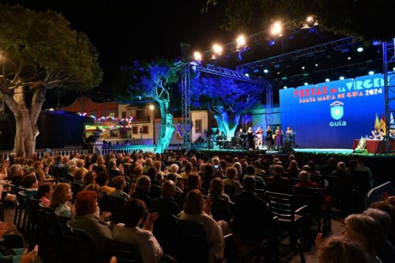
If it’s for a flagship storefront with 3–5 meter viewing distance → P5 will look rough
Outdoor LED Selection Reference (Based on 14 Years of Sostron Projects)
| Core Parameter | Outdoor P3 (Ares) | Outdoor P4 | Outdoor P5 |
|---|---|---|---|
| Pixel Pitch | 3.0mm | 4.0mm | 5.0mm |
| Pixel Density | 111,111/sqm | 62,500/sqm | 40,000/sqm |
| Optimal Viewing Distance | 3–30m | 4–40m | 5–50m |
| Best Use Cases | Flagship storefronts, close-range stage screens, low-height DOOH | Shopping malls, medium commercial plazas | Highway billboards, rooftop screens |
| Typical Cases | France Ares outdoor fixed install | Chile Music Festival (Carbon Series Rental) | Cairo Highway High-Brightness |
| Budget Level | $$$ (High) | $$ (Medium) | $ (Economy) |
| Maintenance Difficulty | High | Medium | Low |
Industry Hidden Rules: The Three Traps Behind Cheap P3
If you receive a quote significantly below market—like $800–$900—be cautious.
Let’s expose the common cost-cutting “tricks.”
1. Fake Pixel Pitch
Some manufacturers sell P3.076 or P3.33 and label it as “P3.”
-
Real P3 = 111,111 pixels/sqm
-
P3.33 ≈ only 90,000 pixels/sqm
You lose 20% pixel count, and future repairs become a nightmare due to non-standard modules.
2. Waterproofing Issues in Generic “Public Mold” Modules
Cheap public-mold kits often skip conformal coating.
-
Outdoor P3 requires IP65 front / IP54 rear
-
Rubber gaskets in cheap modules harden in 6 months
-
Water ingress can fry modules—or worse, cause electrical hazards
3. Industry Standard vs. Sostron Manufacturing Standard
| Dimension | Market Low-Cost Standard | Sostron Standard | Customer Benefit |
|---|---|---|---|
| PCB | 2-layer, 1.0–1.2mm | 4-layer, 1.6mm, gold deposition | 30% better heat dissipation, no blackouts |
| Aging Test | 24h normal temp | 72h (high temp + vibration) | Early defects eliminated |
| Brightness | 4500 nits | 6000+ nits with 20% redundancy | Clear even after years of decay |
| Spare Parts | 1% or none | 3–5% free | 5-year maintenance security |
ROI: Why Paying $200 More Actually Saves You Money
For factories and rental companies, CAPEX is small—OPEX is where the real costs hide.
Let’s calculate a 3-year lifecycle.
1. Electricity Savings
Sostron P3 uses:
-
Common cathode design
-
High-efficiency Meanwell power supplies
→ Saves ~30% energy.
For a 20sqm screen running 12h/day:
-
Savings: $800–$1,000/year
-
3 years = $2,400–$3,000 saved
2. Maintenance Cost
Outdoor repairs require high-altitude tools and lifts.
Low-cost P3:
-
2 repairs/year
-
~$500 each
-
$3,000 over 3 years
Sostron P3:
-
IP65, stable ICs, gold-wire lamps
-
Usually 1 inspection/year
-
~$500 total
3-Year TCO Comparison (20sqm screen)
| Cost Item | Cheap P3 ($900/sqm) | Sostron P3 ($1,200/sqm) | Notes |
|---|---|---|---|
| Initial Purchase | $18,000 | $24,000 | +$6,000 upfront |
| 3-Year Electricity | $12,000 | $8,500 | Saves $3,500 |
| 3-Year Maintenance | $3,000 | $500 | Saves $2,500 |
| Brand Loss | High risk | None | Priceless |
| Total 3-Year Cost | $33,000 | $33,000 | Same cost; better performance |
In the end, the higher-priced screen costs the same, but protects your brand and reduces risk.
The prices mentioned in this article for outdoor P3 LED displays ($900–$2,200 per square meter) are for reference only. Actual purchase costs may vary depending on screen size, configuration, order quantity, shipping, taxes, and supplier policies. Always confirm the final quote with your supplier before making a purchase.
FAQ
Q1: Can outdoor P3 displays withstand typhoons and heavy rain?
A: Yes, but it depends on the cabinet structure.
Sostron’s Ares Series uses high-precision die-cast aluminum cabinets with professional waterproof gaskets and modular design. They pass IP65 spray tests and wind-resistance tests, remaining stable even in coastal typhoon conditions.
Q2: What is your minimum order quantity (MOQ)?
A: We support 1 sqm sample orders. We understand international clients need to verify quality first. For the Hima Series rental screens, small-batch trial orders are also supported.
Q3: Why do some manufacturers quote only $800 but promise a 3-year warranty?
A: That’s a sharp question. Low-cost suppliers usually gamble on probability:
-
Using recycled or B-grade LEDs
-
Betting you won’t experience mass failures within the warranty period
-
Or that high return shipping costs will deter claims
Sostron uses genuine components. Our premium price covers strict QC and real after-sales commitments.
Q4: What permits are needed for installing outdoor P3?
A: Typically, you need approval from local municipal authorities.
Sostron provides full CAD/DWG structural drawings, system connection diagrams, and CE/FCC electrical certifications to help expedite government approvals.
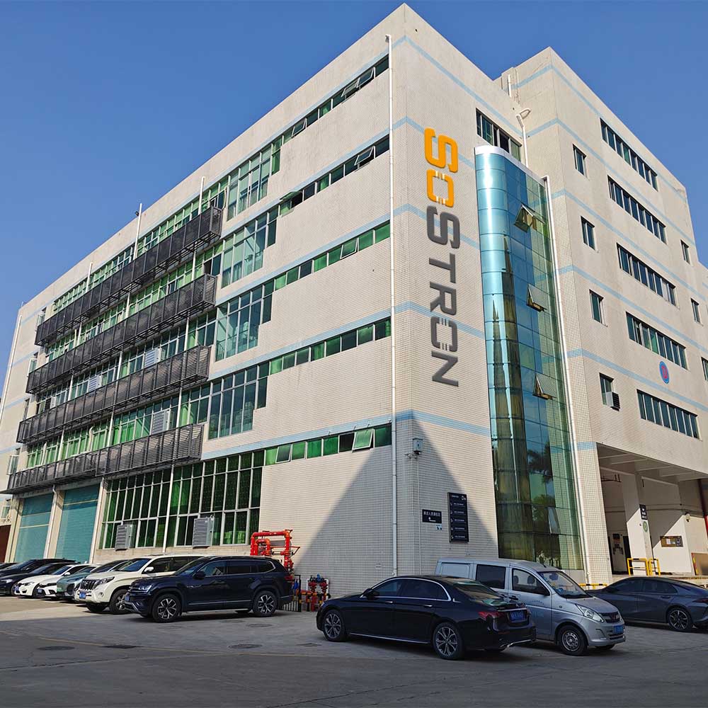
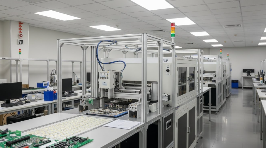
Inside Sostron: Confidence from a 15,000㎡ Smart Manufacturing Base
If you are still hesitating, seeing is believing.
-
15,000㎡ modern production base + 4,000㎡ R&D center
-
National-level high-tech enterprise, not just an assembly plant
Key Facilities
-
Fully automated SMT line: micron-level placement accuracy for every P3 LED
-
Rain simulation lab: high-pressure spray tests for all modules
-
Showroom experience:
-
Crystal Series: ultra-high transparency
-
Carbon Series rental screens: extreme lightweight & thin profile
-
Conclusion & Call to Action
Purchasing an outdoor P3 display is not just buying a glowing panel—it’s investing in your brand’s face for the next 5–10 years.
Don’t let cheap screens with dead pixels or color inconsistencies ruin your advertising campaigns or live events.
Ready to get a real, no-nonsense quote?
References:
NEC (National Electrical Code) – Article 600: Electric Signs