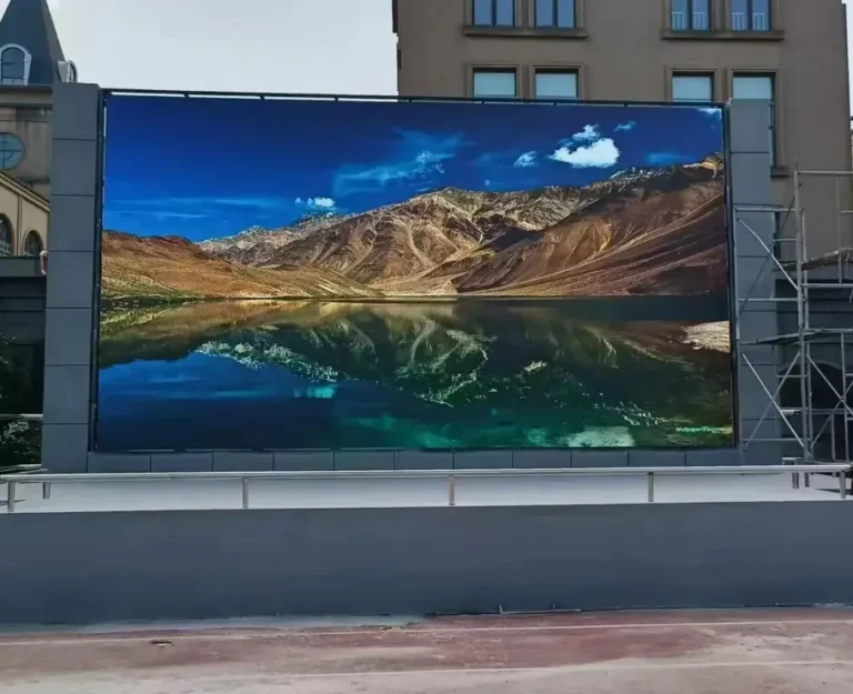
What Is a Modular LED Screen?
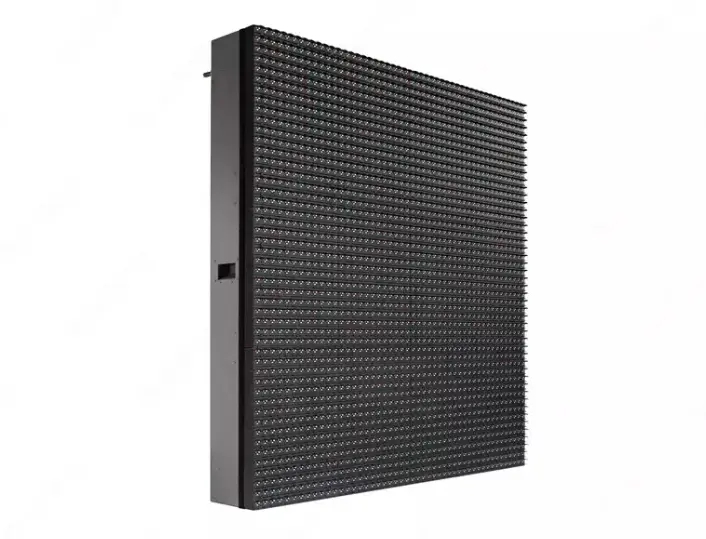
A modular LED screen is a display system built by connecting multiple smaller display units into one larger image surface. Unlike a conventional display with a fixed physical format, a modular LED display can be configured around a project’s required dimensions, aspect ratio, viewing distance, and installation environment, subject to the available cabinet sizes and system design.
The term modular describes how the display is constructed, rather than a single LED technology. A system may use SMD or COB LED packaging, indoor or outdoor cabinets, or fixed-installation or rental hardware. Each configuration serves a different purpose.
For commercial buyers, this distinction matters. An indoor conference-room display has different requirements from a highway advertising billboard, even when both use modular LED technology. Choosing the correct system from the beginning helps reduce specification mismatches, installation complications, and avoidable maintenance costs.
How Does a Modular LED Display Form One Large Screen?
A modular display is assembled in layers. Small LED modules contain the pixels that generate the image. Multiple modules are mounted into a cabinet, and multiple cabinets are aligned and connected to create the complete screen. Power distribution and control equipment allow those individual sections to reproduce one coordinated image.
Samsung’s LED display introduction describes the same general progression from module to cabinet to complete display, while noting that the number of components varies by model.
For a buyer comparing manufacturers, the key is to understand what each quoted component includes. A price for replacement modules cannot be compared directly with a price for complete cabinets, and neither necessarily represents a fully installed display system.
LED Module vs. LED Cabinet vs. Complete LED Screen System
The terminology used in quotations can be confusing, particularly when suppliers use the words panel, module, and cabinet differently. Establishing a shared definition before procurement prevents misunderstandings about quantities, replacement parts, and delivery scope.
| Component | What it is | What to verify before purchasing | Commercial benefit |
|---|---|---|---|
| LED module | A smaller assembly containing LED pixels and associated circuitry | Dimensions, pixel pitch, connectors, and replacement compatibility | Makes targeted repairs possible without automatically replacing an entire cabinet |
| LED cabinet | A structural enclosure holding display modules and associated electronics | Cabinet dimensions, weight, locking system, and service access | Simplifies assembly, transport planning, and maintenance when the design supports it |
| Complete LED screen | Multiple cabinets integrated into one display | Total dimensions, native resolution, control configuration, and structural requirements | Provides a display configured for the intended application |
| Control system | Video processing, sending and receiving equipment, and associated configuration | Supported resolution, signal interfaces, cabinet mapping, and expansion capacity | Helps maintain correct image distribution and simplifies system operation |
| Mounting structure | The framework or support system used to install the display | Load capacity, mounting method, site conditions, and access requirements | Reduces installation risk and supports safe, maintainable operation |
These are functional distinctions; the precise component boundaries vary by product architecture. LG’s direct-view LED technical overview also describes displays as modules assembled within cabinets, with the combined units forming the complete display.
Before approving a quotation, ask the supplier to identify exactly which components are included, which items are optional, and which parts must be ordered separately. This simple step makes competing offers much easier to compare.
How Does a Modular LED Screen System Work?
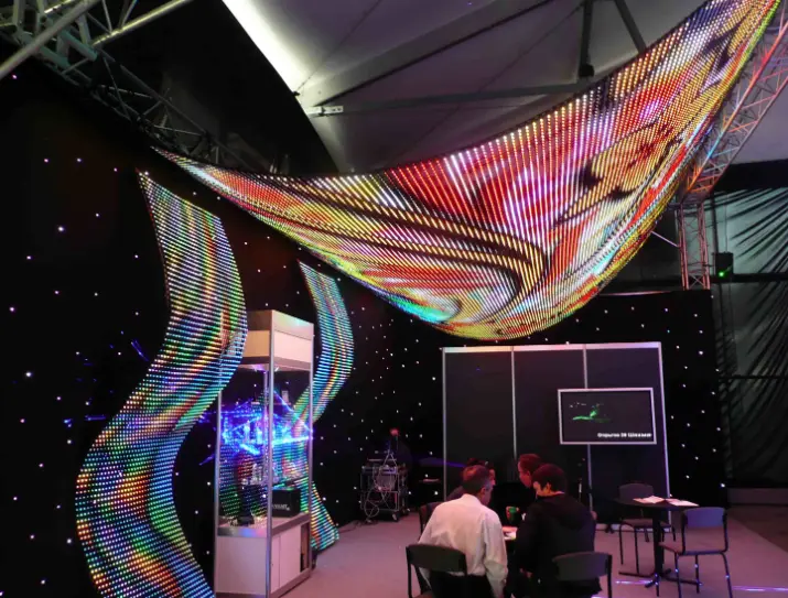
A modular LED display is more than a collection of illuminated panels. Its performance depends on the interaction between the LED modules, cabinet mechanics, power supplies, signal distribution, video processing, and display-control software. If one part is incorrectly specified, the entire installation may suffer from image inconsistencies, difficult maintenance, or unnecessary operating costs.
For system integrators and commercial buyers, understanding this architecture makes it easier to evaluate suppliers, compare technical proposals, and plan future servicing.
LED Modules, Driver ICs and Display Pixels
An LED module contains an array of pixels and the electronic components required to operate them. Each pixel produces the colors needed to display text, graphics, images, and video. Driver ICs regulate LED operation according to the design of the display, while the module’s PCB provides the electrical connections between components.
One specification deserves particular attention: pixel pitch, which is the distance between the centers of adjacent pixels, normally expressed in millimeters. A smaller pixel pitch generally allows more pixels within the same screen area, improving the ability to reproduce fine details when viewers stand relatively close.
However, the smallest available pixel pitch is not automatically the best investment.
| Pixel pitch category | Typical applications | Primary buyer consideration | Commercial implication |
|---|---|---|---|
| Fine pitch, such as P0.9–P1.5 | Premium meeting rooms, control rooms, and close-viewing environments | Fine text, detailed graphics, and viewing distance | Higher pixel density may improve presentation quality but increase hardware cost |
| P1.8–P2.5 | Corporate displays, retail showrooms, and indoor video walls | Balance between viewing distance and image detail | Can provide a practical compromise between visual quality and procurement budget |
| P2.9–P3.9 | Stage displays, rental screens, and selected commercial installations | Audience distance, cabinet design, and operating conditions | Can suit larger viewing distances without paying for unnecessary pixel density |
| P4 and above | Many large-format outdoor advertising and long-distance viewing applications | Viewing distance, content legibility, and environmental requirements | May reduce initial display hardware costs when ultra-fine detail is unnecessary |
These are indicative application groupings, not universal product boundaries. Actual suitability depends on content, viewing distance, brightness, display dimensions, and the selected product.
For buyers, the commercial objective is to specify enough resolution to deliver the intended viewing experience without paying for pixel density that the audience cannot meaningfully benefit from.
Cabinet Frames, Locking Mechanisms and Alignment
An LED cabinet provides the mechanical framework that holds modules and associated electronics in position. Cabinet design influences screen flatness, installation speed, structural requirements, transport efficiency, and access for repairs.
Fixed-installation cabinets and rental cabinets are engineered for different operating conditions. A fixed billboard may prioritize structural stability, weather protection, and convenient maintenance. A rental display used for concerts or exhibitions may place greater emphasis on weight, rapid assembly, locking mechanisms, and repeated transportation.
The cabinet is an engineering decision, not merely a packaging choice.
A poorly matched cabinet configuration can increase labor requirements, complicate installation, or make future servicing more difficult. Buyers should therefore review the cabinet dimensions, material, weight, connection method, and maintenance approach together rather than evaluating each feature independently.
Power Supplies, Receiving Cards and Video Processors
The LED modules create the visible image, but the control and electrical systems determine how reliably the display operates as a complete unit.
- Power supplies: Deliver the electrical power required by the display. Correct sizing supports stable operation and helps avoid underspecified power infrastructure.
- Receiving cards: Distribute and process display data at the cabinet or module level, depending on the architecture. Compatibility is essential when replacing components or expanding a system.
- Video processors and sending equipment: Accept source signals and prepare image data for the display. Their input interfaces, output capacity, and supported resolution influence system integration.
- Control software: Allows authorized operators to configure the screen and manage content, depending on the selected platform and its capabilities.
For multi-screen retail networks, DOOH operators, and corporate environments, control compatibility has a direct operational impact. A system that integrates cleanly with the existing content workflow can reduce commissioning effort and simplify ongoing management.
According to Samsung’s published LED display technical overview, the final screen is assembled from multiple cabinets containing LED modules, with the component count varying by model. This reinforces why buyers should assess the complete system configuration rather than treating every modular LED display as having the same architecture.
How Do Signal Mapping and Color Calibration Create a Uniform Image?
When multiple cabinets form a single LED video wall, each cabinet must display the correct portion of the source image. The control system maps image data to the appropriate display sections, while calibration helps align the appearance of individual modules and cabinets.
Two considerations are especially important for B2B projects.
Signal mapping: The configured screen layout must match the physical cabinet arrangement. Incorrect mapping can cause misplaced content, image discontinuities, or sections displaying the wrong part of a video.
Color and brightness consistency: Differences between modules can make cabinet boundaries visible even when the mechanical alignment is accurate. Calibration helps improve uniformity, but the achievable result depends on the hardware, calibration process, operating conditions, and replacement-part compatibility.
Based on our experience with LED display project planning, these details should be addressed before mass production and installation, rather than treated as minor adjustments after commissioning. For buyers, early verification helps reduce rework, commissioning delays, and disputes over the final image quality.
The practical lesson is straightforward: a modular LED screen should be specified and tested as a complete display system. Individual modules may perform correctly in isolation, yet the assembled screen still requires coordinated mechanical alignment, signal configuration, and image calibration to deliver a consistent result.
What Types of Modular LED Screens Suit Different Projects?
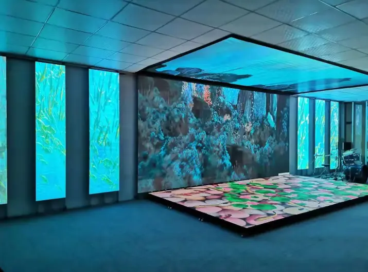
Once the system architecture is understood, the next decision is selecting the display configuration that matches the application. Indoor fixed installations, outdoor advertising screens, rental displays, fine-pitch video walls, and specialized creative displays may all use modular construction, but their mechanical designs and performance priorities differ.
The right choice depends on viewing distance, ambient light, installation conditions, operating hours, maintenance access, and the type of content being displayed.
| Display type | Typical applications | Key specifications to evaluate | Main commercial consideration |
|---|---|---|---|
| Indoor fixed LED | Conference rooms, retail showrooms, control rooms | Pixel pitch, grayscale, calibration, service access | Image quality at the intended viewing distance |
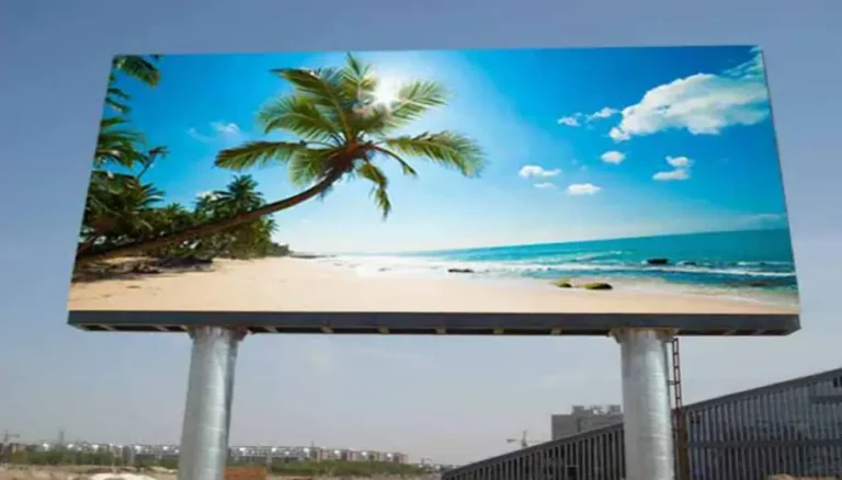
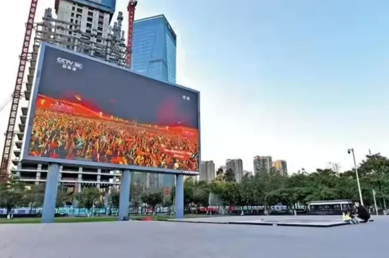
| Outdoor fixed LED | Billboards, highways, building facades | Brightness, IP rating, wind loading, power consumption | Weather exposure, structural engineering, and operating costs |
| Rental LED | Concerts, exhibitions, corporate events | Cabinet weight, locking system, assembly time | Labor, transportation, and repeated setup |
| Fine-pitch LED | Premium meeting rooms and close-viewing installations | Pixel density, calibration, and viewing distance | Resolution requirements versus initial investment |
| COB LED | Command centers, premium corporate displays | Surface protection, repair method, and image quality | Durability requirements and maintenance strategy |
| Transparent LED | Retail windows and selected glass installations | Transparency, brightness, mounting, and visibility | Balancing advertising impact with natural light |
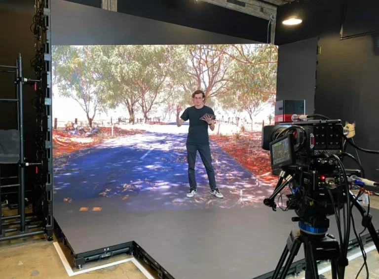
| XR virtual production LED | Film studios and broadcast environments | Refresh rate, scan behavior, grayscale, and camera testing | Camera performance and production workflow compatibility |
These categories are not mutually exclusive. For example, an outdoor display can also be modular, while a rental screen can use fine-pitch LED technology. Select the construction method, pixel technology, and environmental configuration separately.
Indoor Modular LED Screens for Retail, Offices and Conference Rooms
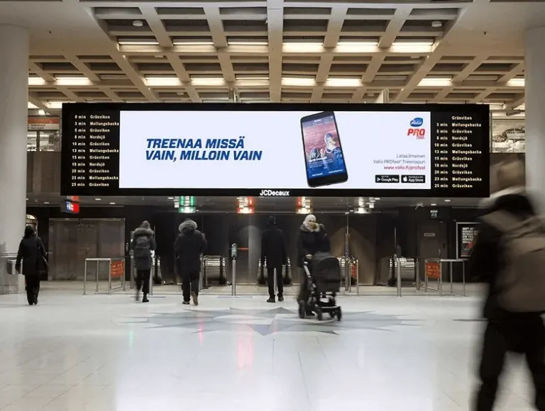
Indoor modular LED displays are designed for environments where viewers may stand relatively close to the screen. Pixel pitch, color consistency, text legibility, and maintenance access therefore deserve particular attention.
For a corporate meeting room, a finer pixel pitch can improve the readability of presentations and detailed charts. In a retail showroom, color reproduction and content visibility may be more important than achieving the smallest possible pixel pitch.
The commercial benefit is straightforward: matching image quality to the viewing environment helps buyers avoid paying for unnecessary resolution or selecting a screen that looks coarse at normal viewing distances.
Before ordering, confirm the screen dimensions, native resolution, source-device compatibility, mounting arrangement, and maintenance clearance. A display that fits the wall but cannot be serviced conveniently is an expensive design oversight.
Outdoor Modular LED Screens for Billboards and DOOH Advertising
Outdoor LED displays face direct sunlight, rain, temperature changes, dust, and wind loads. They need an appropriate combination of brightness, weather protection, cabinet design, power distribution, and structural support.
Brightness is commonly specified in nits. A rated brightness of 5,000–8,000 nits can be a useful starting range for evaluating many outdoor applications, while installations exposed to particularly intense sunlight or demanding viewing conditions may require 8,000–10,000 nits or more. These are indicative selection ranges, not universal requirements or specifications for every SoStron product.
Higher brightness can improve daytime visibility, helping advertising content remain legible in bright surroundings. However, maximum brightness is not the same as normal operating brightness. Automatic or scheduled brightness control can help operators balance visibility, power consumption, and nighttime viewing comfort.
Weather protection also matters. An IP65 rating, where applicable to the relevant enclosure and exposed surfaces, indicates protection against dust ingress and water jets under the specified test conditions. It does not establish resistance to every environmental hazard, nor does it replace structural engineering.
For highway billboards and large DOOH networks, buyers should evaluate the complete installation, including wind loading, mounting structure, electrical supply, maintenance access, and local permitting requirements. These factors can have a greater impact on project feasibility than the LED cabinet price alone.
Rental LED Screens for Concerts, Festivals and Exhibitions
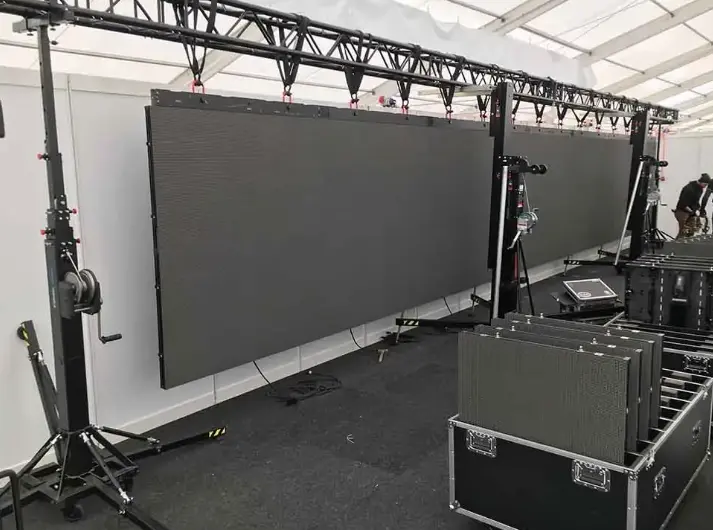
Rental LED displays are designed for projects that involve frequent assembly, dismantling, transportation, and reconfiguration. Cabinet weight, mechanical locking, alignment accuracy, and serviceability can directly influence how efficiently an event team operates.
A lightweight cabinet can reduce handling effort and transportation demands, while a well-designed locking system can help crews assemble the display more consistently. These benefits are particularly relevant when setup windows are short and labor costs are significant.
However, rental suitability cannot be judged by weight alone. Buyers should also assess corner protection, connection reliability, replacement-part availability, cabinet consistency, and the time required to diagnose faults.
For rental companies and AV integrators, the best configuration is one that balances transport efficiency, visual performance, durability, and maintenance requirements across the types of events the company actually serves.
Fine-Pitch, COB and GOB LED Displays for Specialized Applications
Fine-pitch LED displays use closely spaced pixels to produce detailed images at relatively short viewing distances. COB and GOB, meanwhile, describe different approaches to LED packaging or module surface protection.
COB stands for Chip on Board. In this approach, LED chips are mounted directly onto the substrate and covered or protected according to the product design. GOB, or Glue on Board, generally refers to a protective process applied over an LED module’s surface.
Both approaches may offer advantages for particular durability or viewing requirements, but they should not be treated as interchangeable technologies. Actual impact resistance, repair procedures, image quality, and service costs depend on the specific product and its construction.
For command centers, corporate meeting rooms, and premium retail installations, buyers should request the manufacturer’s technical documentation and confirm the repair method before committing to a large order.
Flexible, Transparent and XR LED Displays for Creative Applications
Specialized modular displays serve projects where conventional flat cabinets cannot fully meet the design requirements.
- Flexible LED displays can support curved or creative layouts when the cabinet or module is designed for that purpose. Buyers should verify the permitted curvature, mounting requirements, and mechanical limits.
- Transparent LED displays can preserve some visibility through a display surface, making them relevant to selected retail windows and architectural installations. Actual transparency and image visibility depend on the product and lighting conditions.
- XR virtual production displays are selected for their ability to reproduce suitable backgrounds for camera-based workflows. Refresh rate, scan behavior, grayscale, camera settings, and synchronization should be tested together rather than assessed from one specification alone.
These configurations may require more specialized engineering than conventional flat LED walls. A design review and sample test can help establish whether the intended visual effect is achievable before the full system is manufactured.
How Do You Choose the Right Modular LED Screen Specifications?
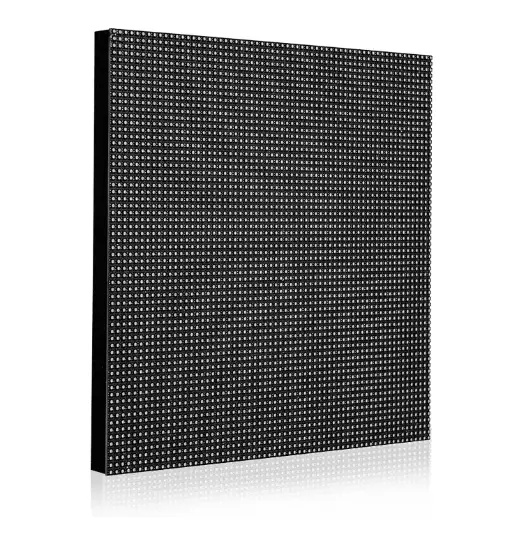
Choosing the right modular LED screen requires balancing image quality, environmental conditions, mechanical design, and total project cost. A specification sheet should be evaluated as a coordinated set of requirements, not a list of isolated numbers.
Choose Pixel Pitch Based on Viewing Distance and Content
Pixel pitch affects pixel density and the level of detail the audience can perceive at a given distance. The ideal selection depends on the screen’s dimensions, content, audience position, and budget.
A presentation screen showing small text to nearby viewers may justify a finer pitch than a highway billboard displaying large advertising graphics to distant traffic.
Before requesting quotations, establish the closest normal viewing distance, typical content, required screen resolution, and intended aspect ratio. These details give manufacturers a practical basis for recommending an appropriate configuration.
Match Brightness and IP Rating to the Installation Environment
Brightness should be matched to ambient light, viewing direction, content, and operating schedule. A higher maximum brightness rating can provide additional headroom in demanding conditions, but it may also increase power requirements when operated at higher output.
The IP rating should reflect the actual exposure conditions. Outdoor installations need suitable protection for the complete installed system, including relevant connectors and enclosures. Coastal locations, high temperatures, dust exposure, and heavy rainfall may introduce additional design considerations.
Ask suppliers to identify the conditions under which their published brightness and protection specifications apply. This makes comparisons more meaningful and reduces the risk of choosing equipment based on a headline specification alone.
Check Native Resolution, Refresh Rate and Grayscale Performance
Native resolution determines how much image information the display can reproduce without relying on scaling. Refresh rate describes how frequently the display updates its image, while grayscale performance affects the reproduction of tonal transitions.
For general advertising, the balance between resolution, viewing distance, and content is often the primary consideration. For broadcast, XR, and camera-facing applications, buyers should also evaluate scan behavior, synchronization, and camera artifacts.
A high refresh-rate specification alone does not guarantee camera-friendly performance. Request a representative camera test under the intended production settings when filming is part of the project scope.
Compare Cabinet Dimensions, Weight and Maintenance Access
Cabinet dimensions determine how the screen can be assembled and how closely its physical size can match the required layout. Weight affects handling, transport, and structural design, while service access determines how easily technicians can reach replaceable components.
Before procurement, confirm:
- Cabinet dimensions and the resulting screen layout.
- Total installed weight and mounting requirements.
- Front-service or rear-service access.
- Availability and compatibility of replacement modules.
- Whether future expansion requires matching cabinets or control hardware.
A modular system can simplify replacement and reconfiguration, but only when the original design allows it. Standardized components and documented compatibility are more valuable than an abstract promise of flexibility.
Evaluate Power Requirements, Cooling and Structural Support
Power requirements affect electrical infrastructure and operating expenditure. Buyers should distinguish maximum rated power from typical operating consumption and request realistic consumption data for the intended content and brightness settings.
For large outdoor screens, structural loading and wind resistance require project-specific assessment. Cabinet dimensions, mounting points, local wind conditions, and the supporting structure all influence the final design.
Thermal management also matters. Equipment operating in hot environments may need specific ventilation, cooling, or derating provisions, depending on the manufacturer’s design and operating limits.
For commercial operators, a correctly engineered installation helps reduce avoidable downtime, unexpected infrastructure work, and long-term operating costs.
Check Controller Compatibility and Future Expansion Options
Expansion is one of the main attractions of modular LED technology, but adding cabinets later is not always a simple plug-and-play process.
The additional cabinets may need compatible receiving cards, matching pixel pitch, appropriate power capacity, supported signal mapping, and consistent color calibration. Older and newer production batches may also exhibit visual differences.
If future expansion is likely, document the original bill of materials, controller configuration, cabinet specifications, calibration data, and replacement-part references. This small administrative investment can save considerable time when the display needs to grow.
Modular LED Screen vs. LCD Video Wall: Which Is Better?
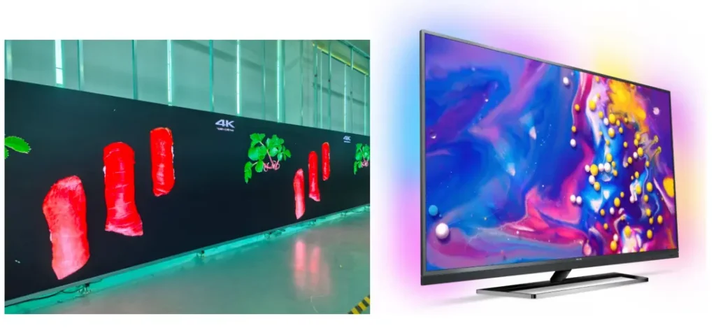
The choice between a modular LED display and an LCD video wall depends on the required size, viewing conditions, installation design, image quality, and total cost of ownership.
An LED video wall creates images using arrays of LEDs across modular display units. An LCD video wall uses multiple LCD panels, whose physical borders generally remain visible between panels.
Neither technology is automatically the right choice for every commercial project.
| Comparison factor | Modular LED screen | LCD video wall | Buyer implication |
|---|---|---|---|
| Visible seams | Can achieve very narrow cabinet boundaries with suitable products and alignment | Physical bezels typically remain visible | LED may suit content that needs to appear across a more continuous image surface |
| Large-format customization | Cabinet arrangements can be designed for a range of screen dimensions | Usually constrained by available panel dimensions and layout | LED offers more configuration flexibility for certain large or unusual formats |
| Close-viewing image detail | Depends on pixel pitch and screen design | Depends on native panel resolution and panel size | Compare actual viewing distance and content rather than technology labels |
| Brightness and environment | Available configurations include high-brightness outdoor displays | Product suitability varies considerably by panel type | Check the exact model’s brightness and environmental ratings |
| Maintenance | Individual modules or cabinets may be serviceable | Individual panels or components may be replaceable | Compare access, repair time, spare parts, and replacement costs |
| Initial investment | Varies with pixel pitch, cabinet design, and project scope | Varies with panel specifications and wall configuration | Compare complete installed quotations |
| Installation requirements | May require cabinet mounting, structural engineering, and display calibration | Requires panel mounting, alignment, and signal integration | Site conditions and screen size can determine the practical installation approach |
Compare Seam Visibility, Screen Size and Installation Flexibility
For large advertising displays, auditoriums, and premium commercial video walls, visible borders can interrupt content that spans multiple sections. A modular LED display with well-aligned cabinets can reduce this effect, making it suitable for large continuous graphics and immersive visual installations.
However, the actual result depends on cabinet tolerances, installation quality, and calibration. Modular construction does not automatically guarantee a perfectly uniform surface.
Compare Maintenance and Total Ownership Cost
The initial quotation is only one part of the investment. Buyers should consider energy consumption, replacement parts, technician access, expected downtime, warranty coverage, and the cost of maintaining the display over its intended service life.
An LCD video wall may be appropriate for a project with standard dimensions and clearly defined viewing requirements. A modular LED system may be more suitable where large dimensions, reduced visible seams, or specialized cabinet configurations are priorities.
The decision should follow the project requirements, not a blanket claim that one technology is always better.
How Much Does a Modular LED Screen Cost?
The price of a modular LED screen depends on more than its physical dimensions. Pixel pitch, brightness, cabinet construction, control equipment, environmental protection, installation requirements, and shipping can all affect the final quotation.
For that reason, a single price-per-square-meter figure is rarely enough to evaluate a commercial project accurately.
Which Specifications Have the Biggest Impact on Hardware Cost?
The following factors typically influence the hardware quotation:
- Pixel pitch: Finer-pitch configurations generally require greater pixel density, which can increase manufacturing cost.
- Cabinet design: Specialized lightweight, curved, front-service, or weather-resistant designs may affect pricing.
- Brightness and protection: Outdoor performance requirements can influence LED selection, thermal design, and enclosure construction.
- Control equipment: Video processors, sending equipment, receiving cards, and software requirements affect the complete system configuration.
- Quantity and customization: Order volume, nonstandard dimensions, cabinet finishes, and project-specific engineering can affect unit pricing.
These are cost drivers, not a verified market price list. Obtain a current quotation for the exact configuration rather than relying on a generic online range.
What Is Included in a Complete Modular LED Display Quote?
A useful quotation should separate the display hardware from the additional items required to deliver an operational system.
| Cost component | What to confirm | Why it matters |
|---|---|---|
| LED display hardware | Modules, cabinets, power supplies, and specified accessories | Establishes the actual display scope |
| Control system | Processor, sending equipment, receiving cards, and software | Prevents missing integration components |
| Mounting structure | Steelwork, brackets, fixings, and engineering responsibilities | Clarifies structural costs and responsibilities |
| Electrical and signal installation | Cables, distribution equipment, and installation materials | Avoids unexpected site expenses |
| Shipping and packaging | Packaging, freight, insurance, and destination charges where applicable | Clarifies logistics exposure |
| Installation and commissioning | Labor, travel, equipment rental, testing, and training | Distinguishes supply-only from turnkey delivery |
| Maintenance provision | Spare parts, warranty terms, technical support, and service arrangements | Helps estimate long-term ownership costs |
For international B2B purchases, buyers should also clarify Incoterms, customs duties, import taxes, delivery responsibilities, and any local certification or permitting requirements that apply to the destination and installation.
How Can Buyers Compare Supplier Quotes on an Equal Basis?
Send each supplier the same project brief and request equivalent technical specifications, quantities, and delivery scope. A low hardware quotation may exclude structural work, control equipment, installation, or spare parts that another quotation includes.
Compare the following before making a decision:
- Exact product series, pixel pitch, and cabinet configuration.
- Brightness, protection rating, and operating conditions.
- Included control equipment and supported resolution.
- Packaging, delivery terms, and installation responsibilities.
- Warranty coverage, spare-part availability, and technical support.
Price note: Any supplier quotation should be treated as configuration-specific. Published online prices may exclude shipping, taxes, installation, and other project costs, so they should not be presented as the final installed price without verification.
How Do You Install and Maintain a Modular LED Screen?
Installation planning begins before the cabinets arrive. Site conditions, structural support, electrical capacity, signal routing, and maintenance access should be reviewed during the design stage.
For international projects, responsibilities between the manufacturer, system integrator, local installer, and end customer should be documented before production begins.
Prepare the Installation Site, Mounting Structure and Power Supply
The installation team should confirm the mounting surface, structural capacity, access routes, electrical supply, and environmental conditions. Large outdoor displays may require professional structural analysis based on local wind loads and building requirements.
Power distribution must be designed around the equipment’s documented electrical specifications, with suitable protection and compliance with applicable local codes.
This planning reduces the likelihood of expensive site modifications after the display has been delivered.
Plan Cabinet Alignment, Cable Routing and Signal Distribution
Cabinets must be installed in the correct sequence and aligned according to the manufacturer’s tolerances. Power and signal connections should follow the documented system design, with appropriate cable management and access for troubleshooting.
Before the display enters service, the team should verify the physical layout against the controller configuration, test image mapping, inspect color uniformity, and confirm that all sections operate correctly.
For large video walls, commissioning records help future technicians identify the original configuration and diagnose faults more efficiently.
Choose Front-Service or Rear-Service Maintenance
Front-service designs allow technicians to access specified components from the display’s front. Rear-service designs require access behind the screen.
The appropriate design depends on the available installation space, screen mounting method, cabinet architecture, and repair procedures. A wall-mounted display in a confined room may benefit from front access, while an outdoor billboard may be designed around a dedicated rear maintenance area.
Confirm the actual service method for the selected model before finalizing the mounting structure. Do not assume that every modular display supports front replacement.
Manage Spare Modules, Calibration and Replacement Compatibility
Spare modules can reduce downtime, but storing parts alone is not enough. Replacement components must be compatible with the display’s hardware and configuration, and they may require calibration to maintain visual consistency.
For operational networks, document spare-part references, cabinet layouts, receiving-card settings, and maintenance procedures. Agree on the warranty process and technical support arrangements before the system is deployed.
This is particularly valuable for DOOH operators and retail chains managing multiple displays across different locations.
How Do You Evaluate a Modular LED Screen Manufacturer?
A reliable supplier should be able to explain how its proposed display meets the project requirements, identify the limits of the configuration, and provide the documentation needed for procurement and installation.
Manufacturer selection should be based on verifiable technical evidence and service capability, not just a polished product catalogue.
Verify Product Specifications, Test Reports and Quality-Control Procedures
Request the technical datasheet for the exact model being quoted. Review relevant brightness, pixel pitch, power consumption, environmental ratings, cabinet dimensions, and operating conditions.
Ask which inspections are performed during production and what the final quality-control process covers. If a supplier claims a particular aging-test duration, certification, or performance result, request supporting documentation rather than assuming it applies to every product.
The goal is to establish whether the delivered hardware matches the contractual specification.
Check Cabinet Drawings, Control-System Compatibility and Spare-Part Availability
Engineering documentation should identify cabinet dimensions, mounting points, electrical requirements, and the planned screen configuration. The supplier should also clarify control-system compatibility, signal interfaces, and how replacement components will be handled.
For projects likely to expand, confirm whether additional cabinets can be integrated with the original system and what matching requirements apply.
This information helps integrators reduce technical uncertainty and protect the long-term maintainability of the installation.
Evaluate Engineering Support, Warranty Terms and After-Sales Service
Before placing an order, establish who is responsible for product selection, installation guidance, commissioning support, and troubleshooting.
Check warranty duration, exclusions, replacement-part procedures, response channels, and any travel or labor charges that may apply. Remote support can be valuable for international installations, but its scope and availability should be confirmed in writing.
For B2B buyers, clear responsibilities are as important as the product itself.
Prepare a Complete RFQ for Your Modular LED Display Project
A structured request for quotation helps manufacturers recommend an appropriate configuration and reduces back-and-forth during the sales process.
Include the following information:
- Project country and installation environment.
- Required screen width, height, and aspect ratio.
- Closest viewing distance and typical content.
- Indoor or outdoor operating conditions.
- Brightness and environmental protection requirements.
- Preferred pixel pitch, if already established.
- Mounting method and maintenance access.
- Control-system and content-management requirements.
- Delivery timeline, budget range, and installation responsibilities.
If some details are not yet known, identify them as pending engineering review. A good RFQ clarifies what is established and what still needs professional assessment.
Why Consider SoStron for Your Modular LED Screen Project?
SoStron positions itself as a global LED display screen manufacturer and commercial display solution provider, offering product selection and project support for different display applications.
The appropriate solution depends on the customer’s requirements rather than a single standard configuration.
Match Indoor, Outdoor, Rental and Specialized Displays to Project Requirements
SoStron’s product portfolio includes the Ares outdoor series, Carbon rental displays, Reta fine-pitch indoor displays, Cobra COB displays, sPad Pro2 flexible displays, and solutions for specialized applications.
Each should be evaluated against the actual project requirements, including viewing distance, installation conditions, cabinet design, maintenance access, and budget.
For example, an outdoor advertising operator may prioritize weather protection, brightness, and operating costs, while an event production company may place greater emphasis on cabinet weight, locking mechanisms, and assembly efficiency.
Coordinate Product Selection, Engineering Support and Installation Guidance
A commercial LED display project may involve more than choosing the display hardware. Buyers may also need assistance with configuration, mounting requirements, control equipment, logistics planning, and installation guidance.
SoStron’s stated service scope includes design, manufacturing, engineering support, installation guidance, and after-sales technical service. Confirm the deliverables and responsibilities applicable to the specific project before ordering.
For international projects, a clearly defined scope of work helps align the manufacturer, local installer, and end customer.
Discuss Control, Maintenance and Long-Term Service Requirements
Before finalizing the specification, discuss the control workflow, content scheduling requirements, replacement-part compatibility, and technical support arrangements.
For multi-site operators, documenting these requirements early can make deployment and future maintenance easier to coordinate.
Request a Modular LED Screen Solution: Provide the application, screen dimensions, viewing distance, installation country, and target timeline so the project team can evaluate the appropriate configuration.
Frequently Asked Questions About Modular LED Screens
1. What Is a Modular LED Screen?
A modular LED screen is a direct-view display assembled from smaller LED modules and cabinets to create a larger screen. Its dimensions and configuration can be adapted to different commercial applications, subject to cabinet sizes and system design. Buyers should evaluate pixel pitch, brightness, control compatibility, mounting requirements, and maintenance access together rather than choosing a display based on size alone.
2. What Is the Difference Between an LED Module and an LED Panel?
An LED module is a smaller assembly containing LED pixels and associated electronics. An LED panel may refer to a module, a cabinet, or a larger display unit, depending on the manufacturer’s terminology. An LED cabinet typically houses one or more modules and provides structural support. Buyers should request a component diagram and bill of materials to ensure that quotations use consistent definitions.
3. Can a Modular LED Screen Be Expanded in the Future?
Yes, many modular LED screens can be expanded by adding compatible cabinets, but expansion is not guaranteed to be straightforward. The additional hardware must fit the system’s mechanical design, control capacity, power distribution, and signal configuration. Differences in production batches or calibration may also affect image consistency. Confirm expansion limits and replacement compatibility before the initial purchase.
4. How Do I Choose the Right Pixel Pitch for a Modular LED Display?
Choose pixel pitch based on the closest normal viewing distance, content detail, screen dimensions, and budget. Fine-pitch displays are often appropriate for close-viewing environments, while larger pixel pitches may be suitable for audiences viewing large screens from farther away. Also consider native resolution, brightness, image calibration, and the type of content displayed. Request a project-specific recommendation instead of relying on pixel pitch alone.
5. How Much Does a Modular LED Screen Cost?
The price depends on pixel pitch, screen size, brightness, cabinet design, control equipment, protection requirements, and order quantity. The final project cost may also include mounting structures, electrical work, shipping, customs charges, installation, and commissioning. Request an itemized quotation based on a complete specification, and verify whether the quoted amount covers hardware only or the full installed system.
Expert Verdict: Specify the System, Not Just the Screen
A modular LED screen is a long-term commercial display investment, not simply a collection of interchangeable panels. Choose the system that fits the viewing environment, engineering constraints, operating requirements, and maintenance plan. Verify component compatibility, compare complete quotations, and document future expansion needs before production starts. Those decisions will do more to protect the project budget and operational reliability than chasing the lowest initial price.
Price Disclaimer: The prices of modular LED screens vary according to pixel pitch, display dimensions, cabinet design, brightness, control equipment, installation conditions, shipping, and other project-specific requirements. Any prices or quotations discussed in this article should be treated as indicative information rather than a guaranteed final cost. Please contact the manufacturer for an up-to-date, itemized quotation based on your exact specifications, delivery destination, and installation scope.
References:
AVIXA — What Is Pixel Pitch? How to Calculate Pixel Pitch