If you need a one-line answer: rent when your display needs to move, buy when your display needs to stay. But that single sentence hides a six-figure decision, so here’s the quick verdict before we go deeper.
| Your Situation | Recommended Option | Why |
|---|---|---|
| Fewer than 10–12 deployments per year, varying venues | Rental LED Screen | Lower CapEx, modular sizing, no storage burden |
| Fixed venue, 24/7 operation, retail/DOOH revenue | Permanent Installation | Lower TCO after ~2–3 years, higher uptime SLA |
| Mixed use—flagship location + seasonal events | Hybrid Model | Own a core wall, rent for peak demand |
That table is the entire article compressed into three rows. Everything below explains the engineering and financial logic behind it, so you can defend the decision in a budget meeting or an RFP review.
We’ve spent the better part of a decade specifying, commissioning, and troubleshooting LED walls for system integrators, touring production houses, and DOOH network operators—and the question “rental or permanent?” is still the single most expensive mistake we see procurement teams make.
Buyers who choose based on price-per-square-meter alone routinely discover, six months in, that they bought a cabinet rated for occasional use and are now running it 16 hours a day, or they rented a full fleet for a project that turned out to be a three-year fixed installation.
Based on our experience commissioning over 200 LED projects across event and fixed-install environments, the right call almost never comes down to budget alone—it comes down to duty cycle, environmental exposure, and how the hardware is actually engineered.
What Actually Separates Rental LED Displays From Permanent Installations?
The terms “rental” and “fixed” don’t describe a business model—they describe two different engineering philosophies, and confusing the two is where most RFPs go wrong.
Cabinet Design & Materials: Die-Cast Aluminum vs Steel Structures
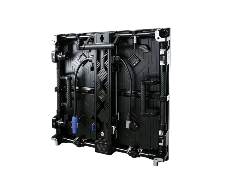
Rental cabinets are almost universally built from die-cast aluminum, typically weighing under 10 kg per panel, with quick-lock or hook-and-buckle systems that let a two-person crew rig or ground-stack a wall in under an hour.
That’s not a convenience feature—it’s the entire value proposition.
A production crew that has to strike a stage in a four-hour overnight window cannot work with bolted steel frames.
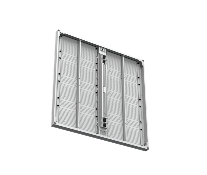
Fixed installations flip the priority: steel or reinforced aluminum structures, wall-mounted or embedded, designed to be installed once and left untouched for a decade.
The feature (steel vs. die-cast) translates directly into the benefit that matters to you: rental aluminum cabinets save labor cost per event, while fixed steel structures reduce structural maintenance cost over the display’s lifespan.
Pixel Pitch Requirements: Why Rental and Fixed Screens Are Engineered Differently
Pixel pitch—the distance in millimeters between LED clusters—governs both resolution and minimum viewing distance.
Rental screens cluster around P2.6 to P3.91, because event audiences typically stand close and expect broadcast-camera-ready image quality for a single night.
Fixed installations span a much wider range, from sub-P2.0 indoor retail walls to P6–P10 outdoor billboards viewed from 30+ meters away, because the viewing distance is fixed and known in advance.
Specifying rental-grade fine pitch for a building façade—or fixed-grade coarse pitch for a trade show booth—is one of the most common (and expensive) sourcing errors we’re called in to fix.
IP Rating & Environmental Durability: Which One Survives 24/7 Outdoor Exposure?
An IP65 rating means full dust protection and resistance to low-pressure water jets—the baseline for any outdoor rental or fixed panel.
But permanent outdoor installations typically demand more: IK10 impact resistance, conformal-coated PCBs against humidity and salt fog, and a wider operating temperature range, because the screen has to survive every season for years, not one weekend.
According to industry durability benchmarks, LED modules rated for continuous outdoor duty carry mean-time-between-failure figures several multiples higher than standard rental-grade panels—a difference that only shows up on your maintenance invoice after 18 months of daily operation.
| Spec Dimension | Rental LED Screen | Permanent Installation |
|---|---|---|
| Cabinet Material | Die-cast aluminum, <10 kg | Steel/reinforced aluminum frame |
| Typical Pixel Pitch | P2.6–P3.91 | P0.9 (indoor)–P10 (outdoor) |
| IP Rating | IP65 (outdoor models) | IP65–IP68 + IK10 impact resistance |
| Assembly Method | Quick-lock, flight-case transport | Wall-mount, rigging, embedded structure |
| Rated Lifespan (LED chip) | 50,000–70,000 hours | 100,000+ hours |
| Serviceability | Front service (fast rebuild) | Front or rear service (planned maintenance) |
Why Choose a Rental LED Screen? 5 Business Benefits Explained
Lower Upfront Capital Expenditure
Renting converts a capital expenditure into an operating expense—you’re not tying up $10,000–$50,000+ in equipment that sits in a warehouse between bookings.
For an event agency running eight to ten shows a year, that capital is better deployed toward creative production or client acquisition.
Modular Flexibility for Creative Shapes and Multi-Venue Deployment
Because rental cabinets are designed to be reconfigured, the same inventory can build a flat backdrop this week and a curved cube stage next week.
That flexibility is a direct commercial advantage: one fleet serves dozens of different client briefs instead of one fixed footprint.
Faster Setup With Quick-Lock and Flight-Case Systems
Sub-hour rigging isn’t a nice-to-have when your venue access window is four hours total, including load-in, sound check, and load-out.
The engineering feature (quick-lock cabinets, flight-case transport) is what makes same-day turnarounds commercially viable.
Access to the Latest LED Technology Without Obsolescence Risk
Rental fleets get refreshed on a rolling basis by the rental house, meaning your production always runs current-generation panels with the latest refresh rate and color calibration—without you absorbing the depreciation.
Why Choose a Permanent LED Installation? 5 Business Benefits Explained
Lower Total Cost of Ownership for High-Frequency Use
Once a screen is running more than roughly 30–35 event-days a year—or 24/7 as in retail or DOOH—the economics flip.
Rental fees compound daily; ownership doesn’t.
Based on our experience with DOOH operators, the crossover point where owning beats renting typically lands between year two and year three of continuous operation.
Continuous Revenue Generation for DOOH Advertising
A fixed panel is a revenue asset, not a cost center—every hour of uptime is inventory sold to advertisers.
That’s a fundamentally different financial model from an event screen, and it’s why DOOH buyers weight reliability specs more heavily than any other criterion.
24/7 Uptime Reliability and Consistent Brand Presence
A permanent installation is engineered around a redundant power supply, hot-swappable receiving cards, and—on higher-end systems—dual signal paths, so a single component failure never takes the whole wall dark during business hours.
For a flagship retail façade or a lobby video wall, that reliability is the brand: a screen that goes black for even one afternoon undermines the exact consistency the client paid for.
Longer Lifespan and Stronger Warranty Coverage
Fixed-install LED chips are commonly rated for 100,000+ hours against the 50,000–70,000-hour rating typical of rental-grade panels, and manufacturers back that with longer warranty terms—often 2–3 years standard versus 1 year on rental inventory.
Run the math and the feature becomes a hard number: at 12 hours of daily operation, a 100,000-hour chip clears two decades of service life before brightness degrades past usable thresholds.
Rental vs Permanent LED Screen Cost Breakdown: The Real ROI Numbers
This is the section most vendor blogs skip, and it’s the one your CFO actually cares about.
| Cost Factor | Rental LED Screen | Permanent Installation |
|---|---|---|
| Upfront cost | $500–$5,000 per day (size/pitch dependent) | $10,000–$50,000+ total system cost |
| Installation | Included in rental fee | 10–20% of hardware cost, one-time |
| Maintenance | Bundled with rental service | Ongoing service contract, $1,000–$5,000/yr |
| Break-even point | N/A—pay-per-use | ~30–35 rental-equivalent uses/year |
| 5-year cost (moderate use, 10 events/yr) | ~$50,000–$150,000 cumulative | ~$25,000–$70,000 total |
| Storage/logistics | Handled by rental house | None—fixed location |
The break-even formula is straightforward: divide your total permanent-install cost by your typical single-event rental cost, and that’s the number of deployments per year at which ownership starts winning.
For most mid-size LED walls, that lands between 30 and 35 uses annually—which is precisely why event agencies running fewer than two shows a month almost always come out ahead renting, while venues running weekly activations or 24/7 DOOH inventory recover their capital within 24–36 months.
One caveat worth flagging: these numbers assume comparable panel quality.
A cheap fixed installation that fails prematurely, or a premium rental fleet booked at peak-season rates, will shift the break-even point meaningfully in either direction—which is exactly why the decision shouldn’t be made on sticker price alone.
Which One Fits Your Business? A Decision Framework by Buyer Type
For System Integrators: Matching Client Requirements in an RFP
Write the spec around duty cycle first, budget second.
If the RFP describes a touring exhibit or a one-off launch event, spec rental-grade cabinets with fast-lock rigging.
If it describes a permanent lobby or façade, spec fixed-grade IP and IK ratings even if the client pushes back on cost—under-specifying here creates warranty and liability exposure for the integrator, not the client.
For Event Production Companies: Building a Fleet vs. Renting Per Project
The fleet-ownership decision hinges entirely on utilization.
Below roughly 15 event-days a year, owned inventory sits idle and depreciates while still costing storage and insurance.
Above that threshold, owning a core inventory of common sizes—while still renting specialty shapes or oversized configurations per project—is where most established production houses land.
For DOOH Advertisers: Why Permanent Almost Always Wins
Ad inventory is sold against guaranteed uptime and audience-measurement consistency.
A rented screen simply can’t offer the contractual reliability that ad-sales teams need to close annual media buys, which is why permanent installation is close to a default choice in this category—the exception being pop-up or seasonal DOOH campaigns tied to a single retail cycle.
The Hybrid Strategy: Own a Core Screen, Rent for Peak Demand
Many of our system-integrator clients now spec a mid-size permanent wall for the client’s day-to-day needs, then supplement with rental panels for annual flagship events.
This captures the low TCO of ownership for baseline use while retaining rental flexibility for the two or three high-visibility moments a year that actually need extra scale.
Common Mistakes B2B Buyers Make When Choosing LED Display Type
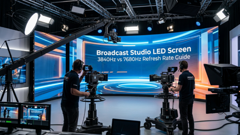
Underestimating Refresh Rate for Broadcast Capture
A panel under 1920 Hz will visibly flicker or band on camera—a dealbreaker for any event being livestreamed or filmed, yet it’s rarely on the buyer’s checklist until the footage comes back unusable.
Ignoring Front vs. Rear Service Access
Rear-service cabinets need wall clearance for maintenance; specifying rear-service in a space with zero clearance behind the wall means every repair becomes a full de-installation.
Choosing on Price-per-panel Alone
The lowest quote rarely accounts for shipping, labor, calibration, or the service contract—compare landed, all-in cost, not the line-item hardware price.
Frequently Asked Questions
Is renting or buying an LED screen cheaper in the long run?
Buying is cheaper past roughly 30–35 uses per year; below that threshold, renting almost always wins on total cost.
What pixel pitch is best for rental LED screens?
P2.6 to P3.91 covers most event use cases, balancing image quality at close viewing distances with panel weight and cost.
Can a rental LED screen be used outdoors permanently?
Technically yes if it’s IP65-rated, but its 50,000–70,000-hour chip life and lighter-duty cabinet weren’t engineered for years of continuous exposure—expect a shorter service life than a purpose-built fixed panel.
How long does a permanent LED installation typically last?
Most fixed installations run 8–10+ years of daily service before a full refresh, assuming proper maintenance and a 100,000-hour-rated chipset.
What’s the break-even point between renting and buying an LED wall?
Divide your total installed cost by your average single-event rental rate—for most mid-size walls that lands around 30–35 event-days per year.
Expert Verdict
Stop asking “which is better” and start asking “what’s my duty cycle.”
Under 15 event-days a year, rent—the flexibility and CapEx savings outweigh everything else.
Over 30 event-days a year, or any 24/7 fixed-location use case, buy—the TCO math becomes undeniable within three years.
Everyone in between should be running a hybrid fleet, not agonizing over a single binary choice.
If you’re still unsure where your project lands, that’s a duty-cycle and RFP-spec conversation worth having with your integrator before a single quote is requested.
Pricing Note:
LED screen pricing varies significantly depending on pixel pitch, screen size, installation environment, cabinet structure, brightness requirements, protection rating, control system, shipping costs, and customization needs. The prices mentioned in this guide are general market reference ranges only and should not be considered as a final quotation. For an accurate project budget, buyers should evaluate the complete solution cost, including LED modules, cabinets, installation, maintenance, and long-term operating expenses.
References:
LED Lighting Technology Overview – U.S. Department of Energy
NIST – Engineering Statistics Handbook: Reliability and Life Testing