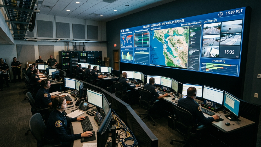
A single dropped frame in a network operations center costs more than a missed highlight reel.A power supply failure in a utility control room is not an inconvenience—it is a liability.The LED video wall sitting at the front of your command center is not a display.It is infrastructure.
Most buyers discover this distinction after the purchase.They spec a commercial-grade fine pitch panel,install it,and spend the next six months chasing flicker artifacts during low-brightness operation,fighting fan noise that drowns out radio communications,or scrambling to restore a wall that went dark because no one planned for redundant signal routing.
This guide is written for the engineers and procurement leads who want to get it right the first time.It covers pixel pitch selection by viewing distance,the reliability architecture that separates 24/7 command center hardware from event-rental gear,and the signal processing stack that keeps every source visible on demand.
What Separates a Control Room LED Wall from a Commercial Display
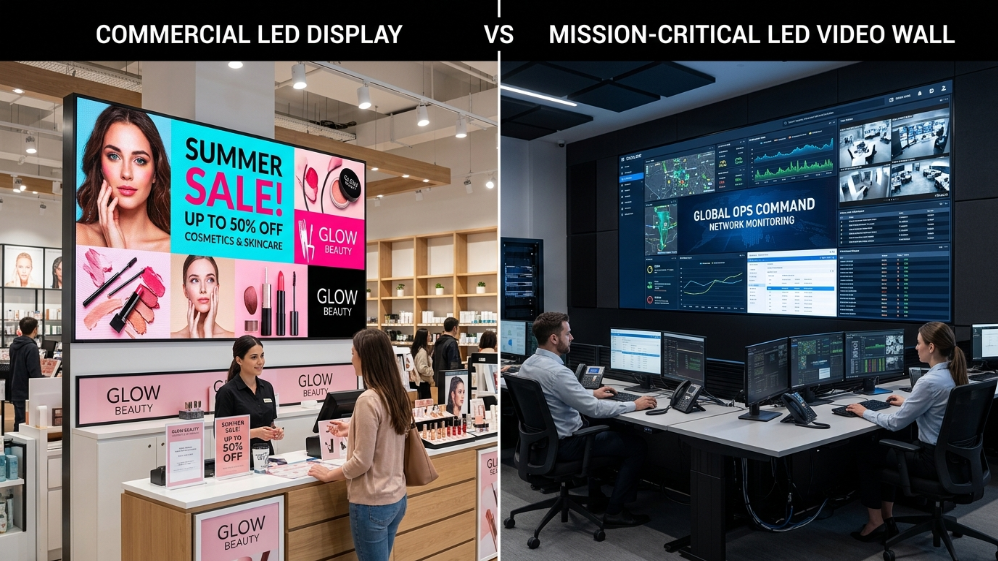
The table below is the fastest way to understand why control room procurement is a different discipline entirely.
Requirement Comparison Table
| Requirement | Commercial/Retail LED Control Room/Command Center LED |
|---|---|
| Pixel pitch | P2.5–P6 typical P1.25–P2.5 required |
| Refresh rate | 1,920–3,840 Hz 7,680 Hz minimum |
| Brightness operating range | 800–1,500 nits 200–800 nits(low-light room) |
| Grayscale depth at 20%brightness | 8-bit(banding visible)14–16-bit(smooth gradients) |
| Cooling | Active fan Fanless/natural convection |
| Acoustic output | 35–50 dB<20 dB |
| Power redundancy | Single PSU 1+1 hot-swap redundant |
| Signal redundancy | Single input Dual-path with auto-failover |
| MTBF | 50,000–80,000 hours≥100,000 hours |
| Serviceability | Rear access Front access mandatory |
Every row in that table represents a failure mode that has shut down a real control room.The refresh rate gap alone explains why security camera feeds—typically 60 fps—produce rolling scan lines on low-spec panels when captured on video.The grayscale depth gap explains why operators in dimmed rooms see posterization on gradient-heavy GIS maps.These are not edge cases.They are the daily operating conditions of a command center.
Pixel Pitch Selection: The Viewing Distance Formula That Actually Works
The industry standard formula is straightforward:minimum viewing distance(meters)=pixel pitch(mm)×3.A P1.5 wall requires a minimum viewing distance of 4.5 m for the human eye to resolve individual pixels as a continuous image.A P2.5 wall pushes that threshold to 7.5 m.
In practice,control room operators sit closer than the formula suggests.A typical NOC or dispatch center places operators 2.5–4 m from the primary display wall.That range demands P1.25 to P1.5 for primary data visualization zones.Secondary overview walls—viewed from 5–8 m—can tolerate P2.0 to P2.5 without visible pixel structure.
The second variable most buyers ignore is content type.A wall displaying 4K video feeds from surveillance cameras has different resolution requirements than a wall rendering a live GIS map with 6-point annotation text.Text legibility at distance follows a different curve than video resolution.For mixed-content walls—part video,part data overlay—the pixel pitch decision should be driven by the smallest text element that operators must read without standing up.
Viewing Distance Reference Table
| Viewing Distance | Recommended Pixel Pitch | Typical Application |
|---|---|---|
| 1.5–2.5 m | P1.25 | Operator workstation rear wall,trading floor |
| 2.5–4.0 m | P1.5 | Primary NOC wall,dispatch center |
| 4.0–6.0 m | P1.8–P2.0 | Secondary overview wall,briefing room |
| 6.0–9.0 m | P2.5 | Large command center rear overview |
| >9.0 m | P3.0+ | Auditorium-style situation room |
One more factor:ambient light level.Control rooms are typically maintained at 200–400 lux—significantly lower than retail or lobby environments.At these light levels,a panel calibrated to 800 nits will appear uncomfortably bright.The ability to dim smoothly to 200–300 nits without grayscale compression is a specification that belongs in every RFP.Panels using common-cathode LED architecture handle this better than conventional designs because the drive current reduction at low brightness does not introduce the color shift that plagues standard SMD configurations.
Reliability Architecture: What N+1 Redundancy Actually Means in Practice
“Redundant power supply”appears in almost every LED spec sheet.What it means in practice varies enormously.
True N+1 power redundancy with hot-swap capability means each cabinet contains two independent power supply units.If one fails,the second carries the full load without any visible interruption—no flicker,no brightness drop,no reboot cycle.Hot-swap capability means the failed unit can be replaced while the wall remains live.This is not a premium feature in a control room context.It is the baseline.
Signal redundancy is less commonly specified but equally critical.A dual-path signal architecture routes the primary video signal and a backup signal simultaneously to the controller.If the primary path fails—a cable fault,a controller card failure,a source device crash—the backup path takes over in under 100 milliseconds.Operators may not notice the switch at all.
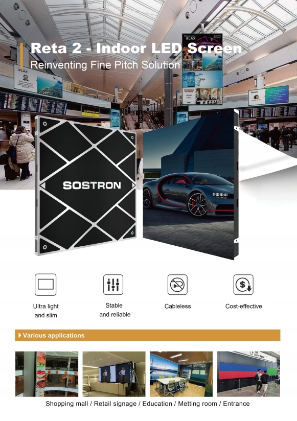
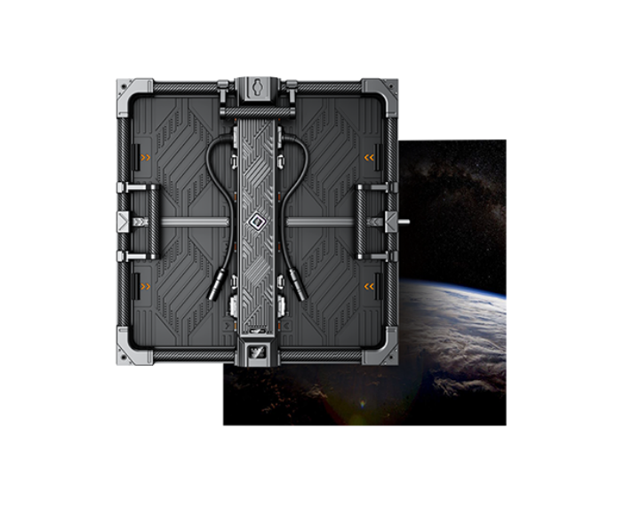
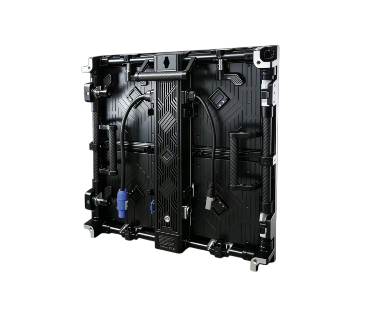
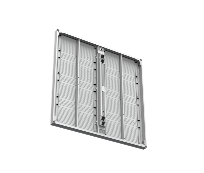
The Sostron Reta 2 implements both.Its 1+1 redundant power configuration is factory-configurable,and the 640×640 mm die-cast aluminum cabinet is engineered for front-access module replacement—a non-negotiable requirement when the wall is flush-mounted against a structural surface with no rear access corridor.The fanless thermal design keeps acoustic output below 20 dB,which matters in radio-equipped dispatch centers where background noise directly affects operator performance.
MTBF figures deserve scrutiny.A published MTBF of 100,000 hours means the statistical mean time between failures across a large population of units—not a guarantee that any individual unit will run for 11.4 years without issue.What it does indicate is component selection discipline:LED binning quality,driver IC thermal ratings,and capacitor specifications.The Reta 2’s 100,000-hour MTBF,combined with its 14-bit processing depth and 7,680 Hz refresh rate,positions it at the upper end of what the fine pitch market currently offers in the P1.25–P2.5 range.
Signal Source Processing: Managing Multiple Inputs Without Losing Situational Awareness
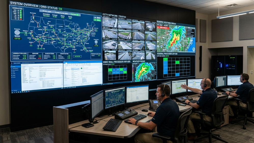
A control room video wall is rarely driven by a single source.A utility operations center might simultaneously display SCADA feeds,IP camera streams,GIS overlays,weather data,and operator workstation outputs—all on the same wall,all requiring independent window management.
The processing layer between your sources and your LED wall is where most control room integrations either succeed or fail.Three capabilities define a competent signal processing stack:
Multi-window layout management.The processor must support simultaneous display of multiple independent video windows at arbitrary sizes and positions,with the ability to save and recall layout presets.Operators switching between incident response modes and routine monitoring should be able to change the entire wall layout in a single keystroke.
KVM extension.In facilities where operator workstations are physically separated from the display wall,KVM-over-IP allows any workstation to push its output to any zone of the wall without physical cable rerouting.This is standard in modern NOC design but requires the LED controller to support the relevant input protocols—typically HDMI 2.0,DisplayPort 1.4,and DVI at minimum,with SDI for broadcast-adjacent applications.
Input failover.If a source device crashes or loses signal,the processor should either hold the last frame,display a configurable fallback image,or automatically switch to a backup source.Blank windows on a live control room wall are operationally unacceptable.
The back half of this guide covers viewing angle requirements for multi-operator environments,the installation tolerances that prevent visible seams at fine pixel pitches,total cost of ownership modeling,and a vendor evaluation framework built around the specifications that actually matter in 24/7 operations.
Control Room Video Wall Buyer’s Guide—Back Half(~1,200 words)
Viewing Angle and Multi-Operator Environments
A single operator sitting dead-center in front of a video wall is the easy case.Real control rooms are not designed that way.A utility operations center might have twelve operators seated across a 180-degree arc,all reading the same wall simultaneously.The display specification that works for the center seat may fail completely for the operator at 45 degrees off-axis.
Fine pitch LED panels have a structural advantage over LCD video walls here:the LED emitter geometry produces consistent color and brightness across a much wider cone.The Reta 2’s 160-degree horizontal and vertical viewing angles mean that an operator seated at 60 degrees off-axis sees the same white point and contrast ratio as the operator directly in front.LCD panels—even high-end IPS—begin showing color shift and brightness falloff beyond 40–50 degrees off-axis,which is why they have largely been displaced in serious command center installations.
The practical implication for room design:LED video walls allow a wider operator seating arc without requiring secondary displays or angled panel sections.This simplifies both the installation and the signal routing architecture.
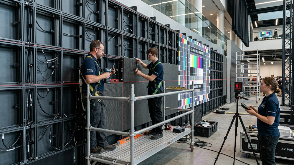
Installation Tolerances: Why Sub-Millimeter Flatness Matters at Fine Pitch
At P2.5 and above,minor cabinet-to-cabinet misalignment is invisible to the human eye at normal viewing distances.At P1.5 and below,a 0.3 mm z-axis step between adjacent cabinets creates a visible bright line that no software calibration can correct.This is a mechanical problem,and it must be solved mechanically.
The sub-frame—the structural grid to which cabinets mount—is the critical variable.CNC-machined aluminum or high-grade steel sub-frames with leveling tolerance of±0.05 mm are the standard for fine pitch installations.Welded steel frames with manual shimming are not.The difference in installed cost is modest.The difference in rework cost when a P1.25 wall shows seam artifacts after commissioning is not.
Floating connector systems,where cabinet-to-cabinet alignment is achieved through high-strength magnetic self-alignment rather than manual bolt adjustment,have become the preferred approach for walls below P1.5.They reduce installation time and eliminate the technician skill dependency that makes manual alignment inconsistent across large installations.
Thermal expansion is the other mechanical variable that gets ignored until it causes problems.A 10-meter-wide aluminum sub-frame expands approximately 2.3 mm across a 30°C temperature swing.For a wall that operates in a climate-controlled room at constant temperature,this is negligible.For a wall in a facility where HVAC fails periodically—or where the room temperature varies significantly between day and night—the sub-frame design must accommodate this movement without transferring stress to the cabinet mounting points.
Total Cost of Ownership: The Numbers That Change the Procurement Decision
Purchase price is the least useful number in a control room LED procurement.The table below models a 10-year TCO comparison across three common approaches for a 4m×2m primary display wall.
| Cost Category | LCD Video Wall | Standard Commercial LED | Control Room LED(e.g.,Reta 2) |
|---|---|---|---|
| Initial hardware | 28,000–45,000 | 22,000–38,000 | 35,000–55,000 |
| Installation&commissioning | 8,000–12,000 | 6,000–10,000 | 7,000–11,000 |
| Annual maintenance(avg) | 4,500–7,000 | 2,500–4,000 | 1,200–2,000 |
| Unplanned downtime(est.10yr) | 15,000–30,000 | 8,000–18,000 | 2,000–5,000 |
| Panel replacement(10yr) | 12,000–20,000 | 5,000–10,000 | 1,500–3,500 |
| 10-year TCO estimate | 67,500–114,000 | 43,500–80,000 | 46,700–76,500 |
The control room LED column’s lower maintenance and downtime figures are driven by three factors:MTBF≥100,000 hours(versus 50,000–70,000 for commercial-grade panels),front-access serviceability,and fanless cooling that removes the highest-failure-rate mechanical component from the reliability equation entirely.
The unplanned downtime estimate deserves particular attention.For a utility control room or emergency dispatch center,a wall outage during an active incident is not just an operational inconvenience—it carries potential liability.Quantifying that risk in dollar terms is facility-specific,but the directional conclusion is consistent:the premium for purpose-built control room hardware pays back within three to four years in most 24/7 operational environments.
Vendor Evaluation Framework: Six Questions That Separate Qualified Suppliers
Before issuing an RFP,ask every candidate supplier these six questions.The answers will sort the field faster than any spec sheet comparison.
What is your published MTBF,and what test standard was used to derive it?Acceptable answers reference MIL-HDBK-217 or Telcordia SR-332.”Our LEDs last 100,000 hours”is a marketing claim,not an MTBF figure.
Does your redundant power configuration support hot-swap replacement under live operating conditions?Ask for a demonstration,not a datasheet reference.
What is your grayscale bit depth at 20%brightness,and how is it maintained?The answer should specify 14-bit or 16-bit processing with a named driver IC.Vague answers about”high grayscale”indicate the supplier does not understand the question.
What is your sub-frame flatness tolerance specification,and how is it verified on-site?Acceptable answers specify±0.05 mm or better with laser measurement verification.”We use experienced installers”is not an answer.
What signal input protocols does your controller support,and what is the failover latency on backup path activation?Failover latency should be under 100 ms.Suppliers who cannot specify this number have not tested it.
What is your on-site response time commitment for critical failures,and do you carry local spare inventory?A 48-hour response time is acceptable for a retail installation.It is not acceptable for a 24/7 command center.
FAQ: Control Room LED Video Wall
Q1: What pixel pitch do I need for a control room where operators sit 3 meters from the wall?
At 3 m,P1.5 is the correct specification for mixed video and data content.P1.25 provides additional headroom if the wall will display fine-detail GIS maps or small-font data overlays.P2.0 is acceptable for secondary overview zones at that distance but will show pixel structure on high-resolution source content.
Q2: Can I use a rental-grade fine pitch LED panel in a permanent control room installation?
Rental panels are engineered for frequent assembly and disassembly,not continuous 24/7 operation.Their MTBF ratings,thermal management,and power redundancy specifications are typically below what permanent control room installations require.The cost saving is real;the operational risk is also real.
Q3: How do I manage 20+ simultaneous video sources on a single LED wall?
You need a dedicated video wall processor—not the LED controller’s built-in input management.Purpose-built processors from Datapath,Barco,or equivalent platforms support 20+independent input windows with layout preset recall,KVM-over-IP integration,and per-input failover logic.Budget this as a separate line item;it typically adds 15–25%to the display hardware cost.
Q4: What causes visible seams on fine pitch LED walls,and how are they prevented?
Seams at fine pitch are almost always mechanical,not electronic.The causes are sub-frame flatness deviation,thermal expansion stress,or cabinet warping from inadequate rear ventilation.Software brightness calibration can reduce the visibility of minor seams but cannot eliminate them.Prevention requires a properly specified sub-frame,floating connector alignment systems,and adequate air gap behind the installation.
Q5: How often does a control room LED wall need recalibration?
Factory calibration holds well for 18–24 months under stable operating conditions.Facilities with significant ambient light variation—or where color accuracy is operationally critical,such as color-coded alert systems—should schedule on-site camera-based recalibration annually.The process takes 2–4 hours and does not require wall downtime if the calibration system supports live-operation adjustment.
Expert Verdict
If your facility runs 24/7 and the display wall is load-bearing infrastructure—not decoration—the procurement decision comes down to two non-negotiable specifications: front-access serviceability and N+1 power redundancy with hot-swap capability.Everything else is negotiable.Those two are not.
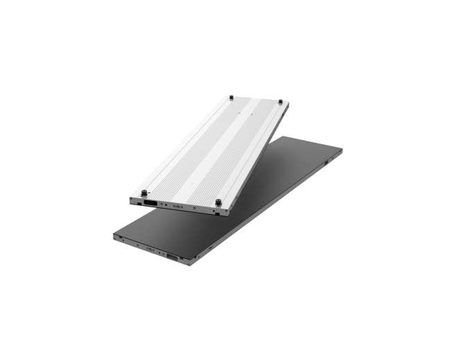
For most command center footprints in the 3–6 m primary viewing distance range,P1.5 at 7,680 Hz with 14-bit grayscale processing covers the full range of operational content types without over-specifying.The Sostron Reta 2 hits that specification at a cabinet weight of 6.5 kg—light enough for single-technician module replacement—with a fanless thermal design that keeps the room quiet and the maintenance schedule predictable.
Buy for the failure scenario,not the demo.The wall that looks best in a showroom at full brightness is not necessarily the wall that performs at 3 a.m.during a grid emergency.Spec accordingly.
References:
AVIXA — Display Image Size for 2D Content in Audiovisual Systems
SMPTE — Motion Imaging Journal & Display Standards