A dead pixel on a COB LED module can almost always be traced to one of three root causes—die bonding failure, driver IC malfunction, or encapsulant degradation—and the fix depends entirely on which one you’re dealing with. Isolated single-pixel failures on coarser pitches (P1.8 and above) are repairable in the field using a hot air rework station; fine-pitch COB (≤P1.2) and any failure involving driver ICs or wire bonding almost always require full module replacement. Here’s the quick-reference breakdown before we get into the procedure:
| Failure Type | Repairable On-Site? | Typical Tool | |
| Single LED chip failure (P1.8+) | Yes | Hot air rework station | |
| Driver IC failure | Rarely | Multimeter + IC replacement | |
| Wire bonding fracture | No | N/A—module swap required | |
| Fine-pitch (≤P1.2) chip failure | Not recommended | Manufacturer service only |
If you’re staring at a screen with a black dot in the middle of a client’s stage backdrop two hours before doors open, you don’t have time for guesswork. You need to know, fast, whether you’re looking at a five-minute fix or a module you should have packed a spare for. That’s the gap most maintenance guides leave open—they tell you COB is “hard to repair” without telling you where the line actually sits.
Based on our experience with field service teams handling COB rental panels across live event and DOOH deployments, the single biggest cause of unnecessary module replacement isn’t hardware failure at all—it’s misdiagnosis. Technicians trained on SMD displays instinctively reach for a desoldering iron the moment they see a dark spot, not realizing that COB’s sealed encapsulant structure makes that approach not just ineffective, but actively destructive. Get the diagnosis wrong on a COB panel and you risk turning a $40 repair into a $400 replacement, or worse, cascading damage into the chips sitting next to it.
Why COB Dead Pixels Are Different From SMD—and Why Most “Quick Fixes” Don’t Work
The Sealed Encapsulant Problem: Why You Can’t Just Swap a Single LED Chip
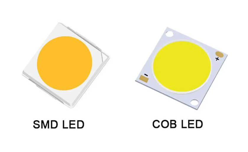
Traditional SMD displays use discrete, pre-packaged LED lamps soldered onto the PCB as independent units. When one fails, you isolate it, desolder it, and drop in a replacement—the same logic as fixing a string of Christmas lights. COB technology eliminates that modularity by design. Chips are mounted directly onto the substrate and sealed under a continuous layer of epoxy resin (the encapsulant), which is precisely the feature that gives COB its advantages: higher pixel density, better impact resistance, and none of the bezel-line visibility that plagues SMD cabinets at close range. The trade-off is that this same sealed structure means there’s no clean access point to an individual chip without disturbing its neighbors. For a B2B buyer, that feature-to-benefit equation matters commercially—COB panels deliver lower long-term failure rates from physical damage in high-traffic rental environments, but it shifts maintenance economics toward module-level repair rather than component-level swaps.
Die Bonding & Wire Bonding Failures—The Hidden Root Cause Behind Most Dead Pixels
According to manufacturing process data shared across COB production lines, the majority of dead pixels don’t originate from the LED chip itself failing in service—they originate at the die bonding or wire bonding stage during manufacturing, where microscopic defects in the bond can lie dormant for months before thermal cycling or current load finally breaks the connection. This matters for diagnosis: a dead pixel appearing in the first 90 days of operation is far more likely to be a latent bonding defect than environmental damage, which is exactly why reputable suppliers offer DOA (dead-on-arrival) and early-failure warranty windows specifically calibrated to this failure curve. External stressors—voltage surges, sustained overheating above the IC’s rated junction temperature, and moisture ingress through a compromised gasket—accelerate the same underlying weakness rather than create a new failure mode.
Diagnose Before You Touch It: A 4-Step Verification Workflow
Skipping diagnosis is the single most expensive mistake we see in COB maintenance contracts. Unnecessary module swaps don’t just waste hardware budget—they introduce secondary problems: brightness mismatch between the new and aged modules, visible color drift, and in fine-pitch installations, flicker that wasn’t there before the “repair.” Follow this sequence in order, low-intervention to high-intervention, before you authorize any physical replacement.
| Step | What You’re Checking | Tool Required | Pass/Fail Indicator |
| 1. Software-level check | Alarm logs, sending/receiving card status, parameter sync | Display control software | No fault flag = move to hardware |
| 2. Visual pattern test | Single pixel vs row/block/cluster failure pattern | Full-color test pattern | Isolated dot = likely chip-level; block = likely IC-level |
| 3. Voltage & continuity test | Power delivery to the affected zone | Multimeter | Voltage present but pixel dark = chip/bond failure |
| 4. Decision matrix | Cost, pitch, failure scope, warranty status | Internal repair-vs-replace matrix | Determines repair method |
Step 1 alone eliminates a surprising share of “dead pixel” service calls—a flagged communication error on the receiving card produces a black square that looks identical to a hardware failure but requires zero soldering to fix. Only once you’ve ruled out the control layer should you move to physical inspection, where the question becomes whether you’re dealing with a genuinely repairable single-chip event or a failure pattern that signals something deeper in the module’s driver architecture.
Can You Actually Repair a Single Dead Pixel on a COB Module? (The Honest Answer)
Once your Step 4 decision matrix points toward “repairable,” the next question is whether your team should attempt it in-house or escalate. The honest answer depends almost entirely on pixel pitch.
When Component-Level Repair Is Possible (and the Pixel Pitch Limit You Should Know)
For coarser-pitch COB modules—generally P1.8 and above—an isolated dead pixel caused by a single chip or bond failure is a legitimate candidate for hot air rework. The encapsulant at these pitches has enough physical clearance between adjacent chips that a skilled technician can localize heat to a single point without disturbing neighboring bonds. This is where COB’s density actually becomes a constraint rather than an advantage: as pitch tightens, that clearance shrinks proportionally.
When It’s Not: Why Fine-Pitch (≤P1.2) COB Almost Always Requires Module Replacement
Below P1.2, chip spacing narrows to the point where a standard rework station’s thermal footprint will almost certainly affect adjacent pixels, and the precision required to reflow a single bond without disturbing a neighbor sitting less than a millimeter away exceeds what field service conditions can reliably guarantee. We’ve seen technicians attempt it anyway under deadline pressure—the result is rarely a clean single-pixel fix and far more often a three-pixel problem where there used to be one. At this pitch, the commercial calculus favors module replacement even when it feels like overkill for “just one dot.”
The Risk of DIY Repair: 3 Mistakes That Permanently Damage a COB Module
Three errors account for nearly every botched COB repair we’ve reviewed. First, removing the protective coating with excessive force or the wrong solvent, which lifts adjacent encapsulant and exposes bond wires that were never meant to see open air. Second, applying reflow heat without a controlled temperature profile—overshooting by even 20–30°C above the rated reflow window can degrade the phosphor coating on neighboring chips, producing a visible color shift days later rather than an immediate failure. Third, skipping the post-repair cure cycle on the UV encapsulant, which leaves the repaired area mechanically weaker and prone to re-failure under the first thermal cycle.
Step-by-Step: Repairing an Isolated Dead Pixel on a COB Module
If diagnosis confirms a single, isolated, repairable failure, here’s the sequence we follow:
Tools required:
Hot air rework station with adjustable temperature control, fine-tip tweezers, a multimeter, isopropyl alcohol (never acetone), UV curing lamp, and matched-bin replacement chips sourced from the same production batch where possible—mismatched binning is the most common cause of a “successful” repair that’s still visibly off-color.
Step-by-step Procedure:
Begin by marking the exact chip location under magnification so there’s no ambiguity once the area is masked. Remove the protective coating in small, controlled sections rather than peeling broadly—pulling too aggressively is the single fastest way to damage adjacent PCB pads. Clean the exposed pad with isopropyl alcohol and let it fully dry; residue here is a leading cause of poor conductivity on the new bond. Set the rework station to the manufacturer-specified reflow profile (typically a 7–10 second dwell once solder reaches reflow temperature) and seat the replacement chip with tweezers, checking alignment against surrounding pixels before the solder sets. Once cooled, apply UV-curing encapsulant over the repaired zone, cure per the resin’s rated exposure time, and lightly sand any excess to restore a flush surface. Power on and run a full-color test pattern—not just white—since color-channel imbalance is far easier to spot against red, green, and blue fields individually than against white alone.
When the Damage Is Too Extensive: Module Replacement Workflow
When the matrix points to replacement—multiple adjacent dead pixels, confirmed driver IC failure, or any fine-pitch chip-level damage—the priority shifts from soldering precision to system-level consistency.
How to Match Replacement Modules for Color & Brightness Consistency
Pull replacement modules from the same binning batch as the original installation whenever your spare parts inventory allows it. Binning consistency—matched brightness and wavelength grouping across LED chips—is what keeps a swapped module invisible against modules that have already aged in service for a year or more. A replacement straight from a different bin will often look correct in isolation and visibly mismatched once installed next to weathered neighbors.
Avoiding Visible Seams and Functional Testing Before Acceptance
After installation, run calibration software to align the new module’s brightness and color output with the surrounding panel before declaring the job complete. Then walk through a structured acceptance check rather than a glance-and-go:
| Test Stage | What to Verify | Pass Criteria |
| Visual integrity | Dead pixels, black blocks, hot pixels | Zero anomalies under full-color pattern |
| Color/brightness match | Seam visibility vs adjacent modules | <3% luminance deviation from neighbors |
| Signal integrity | Data input/output continuity | No latency, dropout, or ghosting |
| Mechanical seating | Module flush fit, locking mechanism | No gaps, no loose fasteners |
Repair vs Replace: A Cost-Benefit Framework for B2B Buyers
For system integrators managing multiple panels under warranty or service contracts, the repair-or-replace decision should be a documented policy,not a case-by-case judgment call. As a general threshold, repair becomes less cost-effective than module replacement once a single module shows three or more dead pixels, or once failures cover roughly 5% of the panel’s visible surface—beyond that point, labor hours on component-level repair typically exceed the cost of a pre-stocked spare module. Negotiating a spare parts ratio of 3–5% of total module count with your COB supplier at the time of purchase, rather than after a failure occurs, is the single highest-leverage move integrators can make to control both repair cost and turnaround time.
Preventing Future Dead Pixels: Maintenance Practices for Long-Term COB Reliability
Thermal management does more to extend COB lifespan than any other single factor—keep ambient operating temperature within the rated range and ensure airflow isn’t obstructed behind the cabinet, since sustained heat above spec is the primary accelerant for both chip degradation and bond fatigue. For rental and touring panels, a monthly visual inspection paired with a quarterly voltage/continuity spot-check catches drift before it becomes a visible failure; fixed installations in controlled environments can typically extend that to bi-annual. Finally, supplier selection matters more than most procurement teams weight it—modules from manufacturers with documented binning consistency and aging/burn-in testing prior to shipment show measurably lower early-failure rates than budget alternatives, even when the on-paper specifications look identical.
FAQ
Can a single dead LED on a COB module be repaired without affecting nearby pixels?
Yes, on pitches of P1.8 and above, using a controlled hot air rework process. Below P1.2, the risk of collateral damage to adjacent chips makes this approach impractical for most field teams.
How many dead pixels are acceptable before requesting a warranty replacement?
Most manufacturers flag anything above 0.1% dead pixel density per panel as a defect eligible for warranty claim—confirm this threshold in your supplier contract, as it varies.
Is GOB repair more difficult than standard COB repair?
Generally yes—the additional protective glue layer in GOB construction requires extra removal and re-curing steps, extending repair time and raising the risk of cosmetic damage to the surface.
How long does professional COB module replacement typically take?
Front-serviceable module designs allow swaps in under 15 minutes; rear-access systems requiring cabinet disassembly can take 45–90 minutes depending on installation complexity.
Can software-based pixel compensation fix a dead pixel without physical repair?
It can mask minor brightness/color imbalance around a small number of dead pixels, but it doesn’t restore the failed LED itself—treat it as a stopgap for distant-viewing applications, not a permanent fix.
Expert Verdict
Don’t reach for a soldering iron before you’ve ruled out a software-level fault—that single step prevents more unnecessary module swaps than any other in this guide. If you’re running fine-pitch COB below P1.2, build your maintenance contracts around module-level repair as the default, not the exception, and negotiate your spare parts ratio at procurement, not after the first failure call.
References:
SMPTE – Society of Motion Picture and Television Engineers