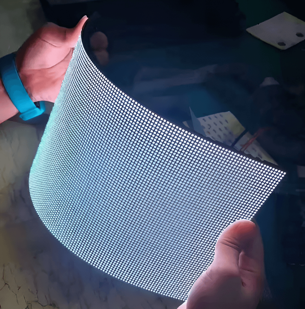
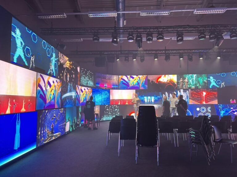
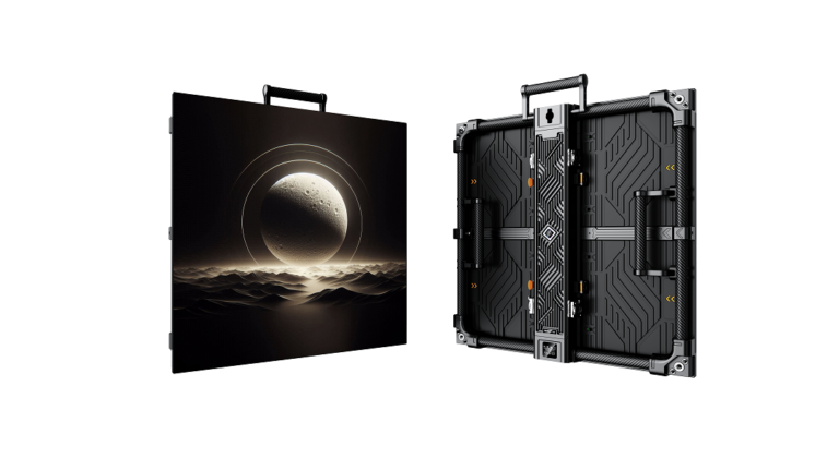
To make LED display, first prepare enough materials. One display covers the frame, display, control, power supply and small accessories.
1. part of the outer frame: special aluminum profile, corners, light steel keel, rear baffle (aluminum plastic plate, Orson plate are OK)
2. Display part: unit board. Accessories include: flat power cord.
3. choke part: choke card, adapter plate and cable arrangement. Note! (the adapter board and cable are not necessary for individual choke cards)
4. power supply part: 220v-5v power supply. 40A and 30A are commonly used. It depends on the working conditions.
5. Small accessories: 16p flat wire, 16p card head and clip, three core numerical wire, DB9 head (needle, hole), DB9 rubber shell, power line, self tapping wire. Strong magnet (supporting column and magnetic disc)
6. Tools: cutting machine, wire pressing pliers, electric soldering iron, wire stripping pliers, screwdriver.

Table of Contents
ToggleSteps for assembling LED display screen
To make a good display, first confirm the volume of the outer frame. Next, I will explain the method of cutting the frame for you. Take the most commonly used 3.5*90 profile and P10 unit plate as an example. The volume of display screen is 2 * 5.
1. Confirm the size of the unit board, which should be very accurate to mm. Take P10 unit board for example: its size is 16cm*32cm.
2. calculate the net size of the height and width of the unit board in the display screen. For example, the height is 2 pieces *16cm=32cm, and the width is 32cm*5 pieces =160cm
3. Subtract 4mm from the calculated net size. As mentioned above, the net size is 32cm*160cm, so the aluminum size should be (32cm-4mm) * (160cm-4mm) =31.6cm*159.6cm. 31.6 and 159.6 are the actual dimensions of aluminum, and 5mm needs to be deducted if the display is more than 3m.
4. Use self tapping to sign the corners and cut profiles, thoroughly tidy up the sundries, and put them face down.
5. Put the unit board in the right direction, and do not make the wrong direction. The place with the pin must face the height of the profile.
6. install the magnet support column onto the unit board and send the magnetic disc into the recess of the nursery column.
7. measure and cut the required length of the light steel keel, put it on the magnet, and try to make the magnet in the center of the keel to avoid deviation.
8. connect the keel with self tapping and frame.
9. Connect the unit board with the flat cable to form a bridge type, and do not let the flat cable have the phenomenon of button.
10. fix the power supply to the appropriate position inside the profile, and confirm the location of the power supply according to the following statement. The power supply is usually placed on the profile below the exposure screen. Pay attention to the insulation with the unit board.
11. connect the power cord. Do not connect the power cord with unclear information. The display screen is a low-voltage office, but the current is very large. It is not allowed to come all the way. The full current of a P10 unit board is 4a, that is, a 40A power supply can carry ten unit boards. The circuit of the display screen is in parallel, that is, the positive pole is connected to the positive pole, the cathode is connected to the cathode, and the common VCC, +5v, +v is the positive pole. GND, com, -v is the cathode. And the positive cathode must not be connected incorrectly, otherwise the unit blackboard will be scrapped. For example, a 40A power supply is equipped with 10 unit boards, which can be divided into three and connected to the 5V power supply once, then connected to the power supply once in three and finally connected to the power supply together. That is to say, there are no more than 4 unit boards in each circuit, so the wire will not be damaged due to excessive current.
12. place the choke card on the input end of the unit board, and be sure to supply 5V power directly from the power supply.
13. the pins of the control card are in order. Such as jk1 JK2…… or j1 J2……JP1. JP2… The position of one should be connected to the uppermost unit board at the input end of the unit board by pressing the arrow.
14. joint signing of the unit board and the choke block: there is a small white letter a around the pin 1 of the ordinary choke card, and there are also such characters at the input end of the unit board. As long as the two A’s are signed with parallel lines, it is accurate.
15. after the above work is completed, the sundries inside the screen must be thoroughly cleaned and tidy to avoid the conductive aluminum powder, iron powder and wire head falling into the circuit board and causing the unit board to be damaged.
16. After finishing the work thoroughly, power on the test, and the premise is to make the value line. Because most digital control business card printing is abnormal before changing the value. Therefore, when there are disordered symbols, dark and bright spots, etc. after power on… Don’t worry about it, as long as you confirm that the positive cathode is not connected incorrectly.
17. welding method of numerical line: common display screen only uses two of the three types below. Extension cable: This is required for every display screen. As the name suggests, its utility is to extend the numerical interface of the choke card to the outside of the display screen. Because your display screen must be sealed at last, you can’t change the data and remove the back cover once! The materials he needs are: a section of three core wire that does not need to be very long, a DB9 pin and a DB9 hole. The number 6789 is marked above the welding place behind each DB9. We only need to countersign three of them. These three are 235. Use one of the three core wires to burn and weld the needle 2 and hole 2. 3 and 3 are welded and 5 and 5 are welded. After finishing, install the plastic shell to the end with the needle (because the hole is inside the screen). It’s OK!
The welding method of the two disjoint straight lines is the same as that of the extension line. The difference is that the two disjoint straight lines use two DB9 holes, and both need to be coated. The materials of the staggered line and the two disjoint lines are the same, the difference is that 2 of the staggered line is connected to 3 of the other, 3 is connected to 2 of the other, and 5 is still connected to 5 Two head rubber shells are also required.
18. the staggered line and the two disjoint lines are still staggered according to the use of the control card.
19. after the above work is done, the rest is adjustment, provided that the power on capacity of the display must be adjusted. As there are many kinds of control cards in the market, I won’t introduce them.
20. After adjustment and test for 2-5 days, if there is no problem, the back cover can be cut and sealed. Finally, we can deliver!

Precautions for making LED display screen
1. the unit board and the choke card must not be connected to more than 5V power.
2. The positive and negative electrodes of all lines must not be connected incorrectly.
3. the sundries in the screen must be cleaned thoroughly.
4. 220V AC, regardless of positive cathode.
Thank you for watching.If you want to know about the 3d led display, you can check this article. Sostron is a provider of commercial display solutions.We provide all kinds of display screens, display leasing and display solutions all over the world.If you have any questions, you can consult us!

About Dylan Lian
Marketing Strategic Director at Sostron


