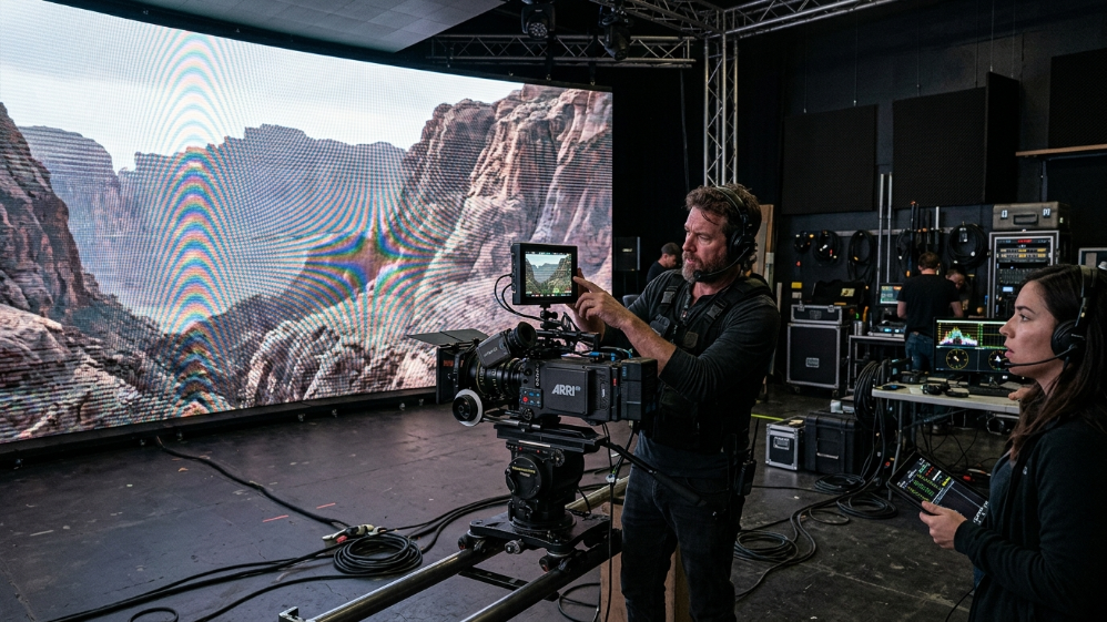
A production designer walks into a test shoot with a $180,000 LED volume. The panel specs look perfect on paper: P1.9, 3,840 Hz refresh rate, “broadcast-grade color accuracy.” The first camera test reveals horizontal scan lines across every frame. The second test, shot at f/2.8, shows moiré interference that makes the background unusable. The third test exposes gradient banding in every shadow. Three failures, three different root causes, one expensive mistake.
This is not a hypothetical scenario. It is the most common outcome when buyers select virtual production LED walls based on marketing claims rather than verifiable technical specifications. The difference between a panel that works in a showroom and a panel that works on a film set comes down to six specifications that most suppliers either misrepresent or do not understand themselves:
Genlock signal compatibility, grayscale bit depth at low brightness, moiré suppression methodology, color volume measurement, processor integration architecture, and shutter angle synchronization.
This guide is written for the technical decision-makers who need to get it right the first time: virtual production supervisors, directors of photography, broadcast engineers, and system integrators specifying LED volumes for ICVFX (in-camera visual effects) workflows.
It covers the specifications that determine on-camera performance, the questions that separate qualified suppliers from resellers, and the integration decisions that make or break a $200,000+ LED volume investment.
Why Standard LED Panels Fail on Camera — and What “Camera-Ready” Actually Means
The term “camera-ready” appears in nearly every LED panel datasheet targeting the virtual production market.
It means nothing without quantifiable specifications.
A panel is camera-ready when it produces zero visible artifacts under the specific camera, lens, frame rate, and shutter angle combination used on your set.
That definition immediately introduces four variables that most spec sheets ignore entirely.
The Three On-Camera Artifacts That Kill a Shot: Moiré, Scan Lines, and Gradient Banding
Moiré Interference
Moiré interference is a spatial frequency phenomenon.
It occurs when the LED pixel grid interacts with the camera sensor’s photosite grid at a frequency that produces visible beat patterns — typically diagonal waves or checkerboard artifacts.
The severity is determined by three factors:
- The ratio between LED pixel pitch and camera sensor pixel size
- The lens focal length
- The aperture setting
A P2.6 panel that produces zero moiré at f/5.6 may become unusable at f/2.0 because the shallower depth of field sharpens the pixel grid into visibility.
Scan Lines
Scan lines appear as horizontal bands moving vertically through the frame.
They are caused by a mismatch between the LED panel’s refresh cycle and the camera’s rolling shutter scan.
If the panel refreshes at 1,920 Hz and the camera captures at 24 fps with a 180-degree shutter angle (1/48 second exposure), the LED scan line moves through the sensor’s exposure window at a rate that produces visible banding.
The artifact disappears at 3,840 Hz and is entirely eliminated at 7,680 Hz — but only if the panel’s scan frequency is synchronized to the camera’s shutter timing via Genlock or an equivalent hardware sync mechanism.
Gradient Banding
Gradient banding is the visible posterization of smooth color transitions, most commonly seen in sky gradients, shadow falloff, and low-luminance scenes.
It is caused by insufficient grayscale bit depth in the LED driver IC or the processing pipeline.
An 8-bit panel produces 256 discrete brightness steps per color channel.
At full brightness, those steps are imperceptible.
At 20 percent brightness — the typical operating level for an LED volume background wall — the steps become visible as distinct bands.
A 16-bit processing pipeline produces 65,536 steps per channel, maintaining smooth gradients even at 10 percent brightness.
How Refresh Rate, Grayscale Depth, and Genlock Interact — and Why You Can’t Optimize One in Isolation
A 7,680 Hz refresh rate does not eliminate scan lines if the panel is not synchronized to the camera’s frame clock.
A 16-bit grayscale pipeline does not prevent banding if the LED driver IC operates at 12-bit.
Genlock synchronization does not prevent moiré if the pixel pitch is too fine relative to the camera sensor resolution.
These specifications are interdependent, and optimizing one while ignoring the others produces panels that fail in predictable ways.
- Camera Flicker: Visible black bars (rolling shutter effect) when filmed.
- Content Loss: Fast-moving content may appear blurry or tearing.
- Not Broadcast Ready: Unsuitable for professional live streaming or TV.
- Flicker-Free: Crystal clear image on all cameras (1/2000s+ shutter speed).
- Smooth Motion: Perfect for fast video playback and sports.
- XR Ready (7680Hz): Essential for virtual production and XR studios.
Relationship Between Specifications and Failure Modes
| Specification | Primary Function | Failure Mode When Absent | Verification Method |
|---|---|---|---|
| Refresh rate ≥7,680 Hz | Completes full scan cycle within camera shutter window | Horizontal scan lines, rolling flicker | High-speed camera test at 120+ fps |
| Grayscale bit depth ≥16-bit | Maintains smooth color transitions at low brightness | Gradient banding, posterization in shadows | SMPTE ramp test at 20% brightness |
| Genlock / tri-level sync | Aligns LED frame draw to camera shutter open | Frame tearing, partial refresh artifacts | Oscilloscope verification of sync signal |
| Pixel pitch vs. sensor resolution | Prevents spatial frequency interference | Moiré patterns, diagonal wave artifacts | On-camera test with target lens at working aperture |
Based on our experience integrating LED volumes for broadcast studios and film productions across North America and Europe, the single most common procurement error is selecting a panel based on refresh rate alone.
A 7,680 Hz panel with 12-bit grayscale and no Genlock input will fail on set.
A 3,840 Hz panel with 16-bit grayscale and hardware Genlock will outperform it in every measurable way.
Pixel Pitch Selection for Every Zone of an LED Volume
An LED volume is not a single surface.
It is a multi-zone environment where each surface — background wall, ceiling, floor, and practical light panels — operates under different viewing conditions and serves a different function in the shot.
Specifying a single pixel pitch for the entire volume is a category error that leads to either over-specification or under-specification.
Background Wall (P1.5–P2.6): Balancing Resolution, Viewing Distance, and Budget
The primary background wall is the surface that appears in the majority of shots.
It is typically viewed by the camera at 3–6 meters and must resolve fine detail without visible pixel structure.
The industry-standard formula for minimum viewing distance is:
Minimum distance (meters) = pixel pitch (mm) × 3
A P1.9 panel requires a minimum viewing distance of 5.7 meters for the pixel grid to become imperceptible to the human eye.
Cameras are not human eyes.
A full-frame cinema camera with a 50mm lens at f/2.8 resolves significantly more detail than the human eye at the same distance.
The practical result is that the pixel pitch × 3 formula underestimates the visible pixel structure on camera by approximately 30 percent.
For camera work, the safer formula is:
Minimum distance (meters) = pixel pitch (mm) × 4
The second variable is camera sensor resolution.
A 4K sensor (3840 × 2160 pixels) capturing a 4-meter-wide LED wall at 5 meters distance sees approximately 960 LED pixels horizontally if the wall uses P1.9.
The sensor undersamples the LED grid by a factor of 2.2:1, which is sufficient to avoid aliasing.
A 6K or 8K sensor at the same distance begins to approach 1:1 sampling, which increases moiré risk significantly.
LED Ceiling, Floor, and Skydome: Why Each Zone Has a Different Pitch Requirement
LED Ceiling
The LED ceiling in a volume is viewed obliquely and at greater effective distance than the background wall.
A ceiling panel mounted 4 meters above the floor and viewed from a camera position 3 meters away has an effective viewing distance of approximately 5 meters.
This allows a coarser pixel pitch (P3.9–P6.0) without visible pixel structure, reducing cost per square meter by 40–60 percent compared to P1.9.
LED Floor
The LED floor faces different constraints.
It must support the mechanical load of talent, equipment, and camera movement.
This requires a ruggedized cabinet design with higher impact resistance (IK08 or better).
Floor panels are viewed downward at close range (1–3 meters) but are almost never the primary focus of the shot.
A P2.9–P3.9 pitch is sufficient for most applications.
The critical specification for floor panels is not pixel density — it is the diffusion layer that prevents specular reflections from creating hotspots in the shot.
The Moiré Risk Formula: How to Calculate Safe Pixel Pitch for Your Camera and Lens
Moiré occurs when the spatial frequency of the LED pixel grid approaches the spatial frequency of the camera sensor’s Bayer filter array.
The formula for moiré risk assessment is:
(LED pixel pitch in mm) ÷ (sensor photosite pitch in mm) = interference ratio
Risk interpretation:
| Interference Ratio | Risk Level |
|---|---|
| 0.8 – 1.2 | High Risk |
| Below 0.5 | Low Risk |
| Above 2.0 | Low Risk |
A full-frame sensor (36mm × 24mm) at 4K resolution has a photosite pitch of approximately 0.009 mm.
A P1.9 LED panel has a pixel pitch of 1.9 mm.
The interference ratio is:
1.9 ÷ 0.009 = 211:1
This is well outside the interference zone, which is why P1.9 is a safe choice for full-frame 4K cameras.
The second mitigation tool is lens aperture.
Stopping down to f/5.6 or f/8 increases depth of field and sharpens the LED pixel grid into visibility, which increases moiré risk.
Opening up to f/2.0 or f/2.8 creates bokeh that diffuses the pixel grid, which reduces moiré risk.
XR LED Volume Pixel Pitch Selection Matrix
| Volume Zone | Recommended Pitch | Min. Viewing Distance | Camera Sensor | Moiré Risk | Aperture Guidance |
|---|---|---|---|---|---|
| Primary background wall | P1.5 – P1.9 | 3 – 5 m | Full-frame / S35 at 4K+ | Low | f/2.0 – f/4.0 safe |
| Secondary background | P2.0 – P2.6 | 5 – 8 m | S35 at 4K | Medium | f/2.8+ recommended |
| LED ceiling / skydome | P3.9 – P6.0 | 4 – 10 m (oblique) | Any format | Low | Any aperture |
| LED floor | P2.9 – P3.9 | 1 – 3 m (downward) | Any format | Low | Any aperture |
| Practical light panels | P1.9 – P2.6 | < 2 m | Any format | High | f/2.8+ with diffusion filter |
Moiré risk assessed at typical production apertures. Interference ratio = LED pixel pitch (mm) ÷ sensor photosite pitch (mm); values 0.8–1.2 are high-risk regardless of zone.
Genlock and Camera Shutter Sync — The Spec That Makes or Breaks ICVFX
Genlock is the most misunderstood specification in the virtual production LED category.
Suppliers claim Genlock support without specifying the signal format, frame rate compatibility, or implementation layer.
Buyers assume that “Genlock compatible” means the panel will synchronize to their camera.
The result is a $200,000 LED wall that tears on every take because the Genlock signal is routed to the wrong device in the signal chain.
Genlock vs. Framelock vs. ShutterSync — Three Different Problems, Three Different Solutions
Genlock
Genlock is the synchronization of the LED panel’s frame draw cycle to an external reference clock.
The purpose is to align the LED’s refresh timing to the camera’s frame timing.
Without Genlock, the camera may capture the LED mid-refresh, producing partial frame artifacts or tearing.
Framelock
Framelock is the synchronization of multiple LED panels to each other.
In a large LED volume with 50+ cabinets, each cabinet’s controller must draw its portion of the image at exactly the same time as every other cabinet.
ShutterSync
ShutterSync is a Brompton-specific feature that goes one step further than Genlock.
It synchronizes the LED panel’s scan line timing to the camera’s rolling shutter scan.
This eliminates horizontal banding that can occur even when Genlock is correctly configured.
ShutterSync requires a Brompton Tessera SX40 or R2+ processor.
Shutter Angle Math: The Formula Every DP Needs on Set
The minimum refresh rate your LED wall must sustain is:
Minimum Refresh Rate = Frame Rate × (360 ÷ Shutter Angle) × Safety Factor (2)
At 24 fps with a 180° shutter:
24 × (360 ÷ 180) × 2 = 96 Hz minimum
At 24 fps with a 270° shutter:
24 × (360 ÷ 270) × 2 = 64 Hz minimum
The real issue is PWM dimming behavior at low brightness.
Standard commercial LED panels rated at 3,840 Hz can drop their effective refresh rate by 60–70% when dimmed to 30% output.
A panel that behaves like a 1,152 Hz display in a dark scene will produce horizontal scan lines regardless of what the specification sheet says.
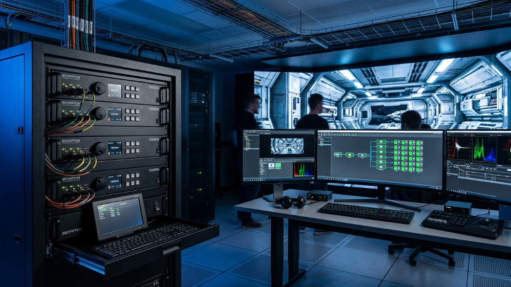
Brompton Tessera Integration: The Complete Signal Chain
| Signal Chain Layer | Component | Function | Critical Specification |
|---|---|---|---|
| Sync source | Camera body (ARRI / RED / Sony) | Genlock reference output | Tri-level sync, <1 ns jitter |
| Sync distribution | Blackmagic / AJA sync generator | Distribute reference to all devices | Phase-locked distribution |
| Processing | Brompton Tessera SX40 | Frame management, EBD, OSCA | Full 16-bit processing pipeline |
| Receiver card | Hima XR R2+ | Per-cabinet calibration storage | Native ShutterSync® support |
| Display surface | Hima Series XR panels | Final light output | 7,680 Hz, 16–22 bit, 99% DCI-P3 |
| Calibration system | Brompton Hydra / OSCA | Per-pixel uniformity correction | Coefficients stored on R2+ card |
The SX40’s Extended Bit Depth (EBD) feature is where the 16–22 bit grayscale specification becomes practically meaningful.
Standard LED processing pipelines truncate grayscale data to 8 or 10 bits before transmission to the panel.
EBD preserves the full bit depth through the entire chain.
OSCA addresses the second major failure mode: panel-to-panel color uniformity.
Sostron Hima Series XR: What the Spec Sheet Actually Means
Core Specifications
- Pixel pitch: P1.5 / P1.9 / P2.6 (primary background walls)
- P2.9 / P3.9 (ceiling and floor panels)
- Refresh rate: 7,680 Hz sustained
- Grayscale depth: 16–22 bit
- Color gamut: 99% DCI-P3
- Processor compatibility: Brompton Tessera SX40 + R2+ receiver cards
- Cabinet weight: 6.5 kg
- Maintenance: Front-access module replacement
The DCI-P3 figure deserves emphasis.
Most LED panels are specified against sRGB, which covers roughly 72% of DCI-P3.
A panel claiming “wide color gamut” against sRGB is not equivalent to a panel calibrated to DCI-P3.
For productions with HDR deliverables, this distinction is the difference between passing and failing a platform’s technical review.
Frequently Asked Questions
Q1: Can I use a standard commercial LED wall for virtual production if I add a Brompton processor?
The processor handles synchronization and calibration, but it cannot compensate for panel hardware limitations.
The processor amplifies a good panel; it cannot rescue a bad one.
Q2: How do I calculate whether my LED wall will cause moiré with my specific camera?
Divide the LED pixel pitch in millimeters by your camera sensor’s photosite pitch in millimeters.
If the result falls between 0.8 and 1.2, you’re in the high-risk interference zone.
Mitigation options:
- Open the aperture
- Increase focal length
- Specify a finer pixel pitch
Q3: What’s the minimum LED volume size for a functional single-talent setup?
A functional interview or single-talent setup requires approximately:
- 6m wide × 3m tall primary background wall
- Ceiling panels if overhead lighting replacement is required
Feature productions typically specify 20m+ curved backgrounds.
Q4: Does 99% DCI-P3 coverage mean the LED wall can replace all practical lighting?
No.
LED volumes replace background environments and contribute ambient fill.
They cannot replace key lighting for talent.
Q5: How long does Brompton OSCA calibration take for a large LED volume?
- 100 m² volume: 4–6 hours initial calibration
- Single cabinet replacement: 30–45 minutes recalibration
Build calibration time into your pre-production schedule.
Expert Verdict
Virtual production LED specifications are not marketing differentiators — they’re production insurance.
A panel that fails at 30% brightness on a dark atmospheric set, or produces moiré with a full-frame sensor at 50mm, doesn’t get a second chance on a $50,000-per-day stage.
The Hima Series XR’s combination of 7,680 Hz sustained refresh, 16–22 bit EBD-compatible grayscale, and native Brompton Tessera integration addresses the three failure modes that actually shut down productions:
- Scan lines
- Shadow banding
- Frame tears
The 99% DCI-P3 coverage closes the loop for HDR deliverables.
For permanent LED volume installations:
- Start with P1.9 for the primary background wall
- Use P3.9 for ceiling panels
For touring or rental systems:
- P2.6 at 6.5 kg per cabinet provides a practical balance between logistics and performance
Specify to the numbers. The failure modes are well-documented, and the math doesn’t negotiate.
References:
SMPTE Virtual Production Study Group
In-Camera Visual Effects (ICVFX) Production Test