Every broadcast engineer making a display purchase decision faces the same core question—not “which screen looks best?” but “which screen will perform flawlessly at the moment I cannot afford failure?” A broadcast LED video wall that produces moiré patterns on camera, miscalibrated skin tones against Rec.709 reference, or drops signal during a live national feed is not a display problem. It is a revenue, reputation, and contract liability. This guide is written to give you—the system integrator, technical director, or studio architect—the precise engineering framework to specify a TV studio display that eliminates those risks before the first camera ever rolls.
Quick-Reference Spec Floor for Broadcast LED Video Walls
| Parameter | Minimum Broadcast Threshold | Why It Matters |
|---|---|---|
| Pixel Pitch | ≤P1.5mm (close-camera zone) | Prevents moiré at zoom-in focal lengths |
| Refresh Rate (PWM) | ≥3,840 Hz | Eliminates scan lines across all professional shutter speeds |
| Color Space Calibration | Rec.709/Rec.2020 factory-certified | Ensures skin tones match broadcast delivery standard |
| Grayscale Depth | 16-bit | Preserves shadow/highlight detail at any dimming level |
| Anti-Reflectance (mask) | ≤5% surface reflectance | Absorbs studio light rigs; prevents camera lens bloom |
| Signal Redundancy | Dual-path hot-swap (N+1) | Zero-frame failover if primary processor fails |
| Genlock Input | Tri-sync/Bi-sync supported | Locks display refresh to camera frame timing |
Why Standard LED Displays Fail in Broadcast Environments (And What “Broadcast-Grade” Actually Means)
Walk into any trade show and every LED vendor claims their product is “broadcast-grade.” Almost none of them can define what that means in engineering terms. Based on our experience with broadcast studio deployments across North America, Europe, and Southeast Asia, the failure points cluster around a single truth: standard commercial LED displays are designed for human eyes, not camera sensors. These are fundamentally different optical systems, and confusing them is the most expensive specification error an integrator can make.
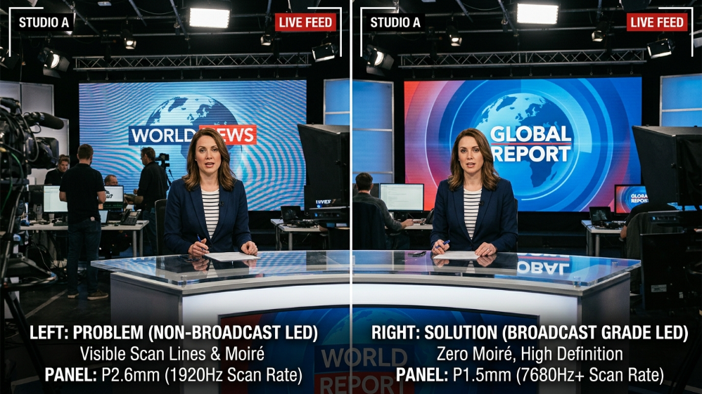
The human visual system has a flicker-fusion threshold of approximately 50–60 Hz. A display running at 960 Hz looks perfectly smooth to any observer in the studio. A Sony FX9 or ARRI Alexa Mini LF operating at a 1/500s shutter speed, however, will expose each frame while the LED panel’s Pulse-Width Modulation (PWM) cycle is mid-pulse—capturing a partial illumination state that renders on screen as a rolling dark band or scan line. This is not a camera defect. It is a fundamental physics mismatch between PWM dimming frequency and camera shutter timing.
The fix is not complicated, but it must be specified upfront. A display running at ≥3,840 Hz PWM refresh will complete multiple full cycles within even the shortest professional shutter duration, eliminating visible artifacts across every standard frame rate from 24fps to 120fps. A 1,920 Hz display—common in mid-range commercial signage—will fail this test at multiple shutter speeds. The cost difference between driver IC tiers that deliver 1,920 Hz versus 3,840 Hz is approximately $15–$45 per square meter. On a 40m² news studio backdrop, that is a $600–$1,800 delta. Compared to the cost of a re-shoot, a damaged client relationship, or a live broadcast incident, it is the single highest-ROI line item in the specification.
The Hidden Camera-LED Compatibility Chain Most Vendors Never Explain
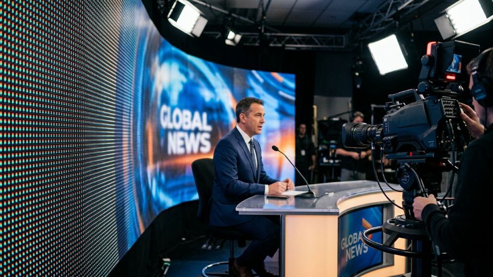
The refresh rate conversation is necessary but not sufficient. Moiré effects—the shimmering wave patterns that appear when a camera sensor’s pixel grid interferes with the LED panel’s pixel structure—are a spatial problem, not a temporal one. They require a separate solution: pixel pitch selection based on actual camera-to-wall distance and lens focal length in use.
Camera Sensor to LED Compatibility Chain:
- Camera sensor pixel pitch
- LED panel pixel pitch
- Shooting distance
- Lens MTF
- Moiré risk
A P2.5 panel looks pristine to a camera locked at 5 meters on a wide angle. Zoom that lens to 85mm for a talent close-up and the LED background is now resolving at effective distances under 2 meters—and moiré may appear. This is why broadcast studio specifications always require tighter pitch (P1.2–P1.5) than a comparable control room installation, despite similar physical viewing distances. Cameras zoom unpredictably. The specification must account for worst-case focal length, not average.
The third variable in the chain is Genlock. Even with correct pixel pitch and high PWM frequency, a display running in “free-running” mode—where its refresh cycle is independent of the camera’s frame timing—can produce intermittent rolling bars on certain frame rates. Genlock synchronizes the LED wall’s internal clock to the broadcast reference signal, locking refresh to camera frame rate and eliminating the frame-timing mismatch entirely. Any broadcaster screen deployed in a live production environment without Genlock capability is operating with an unacceptable technical risk.
How to Verify a Vendor’s “Broadcast-Grade” Claim — The 5-Point Engineering Checklist
Before issuing an RFQ, require documented answers to these five questions:
- PWM Refresh Rate at Minimum Brightness — Many panels achieve high refresh rates at full brightness but drop to 960 Hz or 1,920 Hz when dimmed below 30%. Studio environments routinely operate at 20–40% brightness. Request data across the full dimming curve.
- Genlock Input Type — Confirm support for Tri-Sync (NTSC/PAL black burst) or Bi-Sync (HD tri-level). Generic HDMI sync is insufficient for broadcast-grade deployment.
- Factory Calibration Report (Rec.709) — Ask for per-panel Delta E ≤1 calibration certificates traceable to the D65 white point reference. “Color accurate” without a certificate is marketing language, not an engineering commitment.
- Matte Black Mask Reflectance Value — The physical mask material between LED pixels should have surface reflectance ≤5%. Ask for the measured value. High-gloss masks will produce specular hotspots under studio lighting that no color grading pipeline can correct.
- Hot-Swap Redundancy Architecture — Confirm N+1 power supply configuration and dual independent signal path with automatic failover. Ask specifically: “What is the failover time in frames if the primary signal processor fails?” The correct answer is zero perceptible frames.
Fine Pitch LED for Studio: Choosing the Right Pixel Pitch for Your Camera Distance
Pixel pitch selection for a TV studio display is not a resolution exercise—it is a risk management exercise. The question is not “how sharp does it look?” The question is “at what minimum camera-to-wall distance and maximum zoom level can this display perform without moiré under any shooting condition?”
The Pixel Pitch–Viewing Distance Formula—And Why Broadcast Breaks the Rules
The standard industry formula (minimum viewing distance in meters = pixel pitch in mm × 1,000 / 1,000 = pitch in mm × a correction factor) gives clean, predictable results for fixed-audience environments like control rooms and corporate lobbies. Broadcast studios violate nearly every assumption that formula relies on.
In a control room, the operator’s viewing position is known and fixed. In a live studio, the camera operator adjusts zoom in real time, the director calls unexpected tight shots, and a handheld camera may swing within 1.5 meters of the background during a walk-and-talk segment. The display must resolve cleanly under all of these conditions simultaneously.
Pixel Pitch Comparison for Broadcast Studio Applications
| Pixel Pitch | Optimal Fixed Viewing Distance | Minimum Camera Distance (Safe Zone) | Recommended Studio Use Case | Relative Cost Index |
|---|---|---|---|---|
| P0.9–P1.2 | 0.9–1.2m | <1.0m | Ultra-close-up XR stages, talent close-up zones | $$$$ |
| P1.5 | 1.5m | 1.5–2.0m | Primary news studio backdrop, anchor desk | $$$ |
| P1.8–P1.9 | 1.8–2.5m | 2.5–3.0m | Mid-distance studio sets, interview backgrounds | $$ |
| P2.5 | 2.5m+ | 4.0m+ | Wide-shot studio walls, controlled fixed-angle sets only | $ |
For most broadcast studio primary backgrounds—the curved LED wall behind a news anchor, the IMAG display on a live event stage, the background volume in an XR production—P1.5 represents the optimal price-to-performance threshold. It safely accommodates telephoto close-ups from 1.5 meters while avoiding the thermal management complexity and higher cost of sub-P1.2 configurations.
One critical packaging consideration for 2026 specifications: COB (Chip-on-Board) technology, where LED chips are bonded directly to the PCB and sealed with epoxy resin, offers meaningfully superior moiré resistance compared to traditional SMD packaging at equivalent pixel pitches. COB eliminates the visible black gap structure between individual LEDs that creates the spatial frequency interference responsible for camera moiré. For broadcast applications where the display occupies more than 50% of camera frame, COB at P1.5 outperforms SMD at P1.2—and at lower total cost.
The Recommended Solution: Sostron Carbon Pro & Hima XR Series for Broadcast Studio Environments
Based on the technical requirements outlined above, two product families from Sostron’s lineup are specifically engineered to meet broadcast-grade deployment standards.
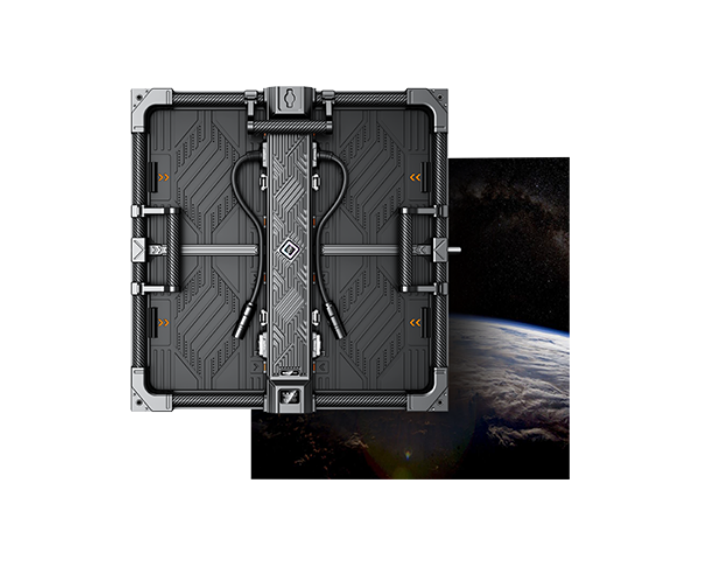
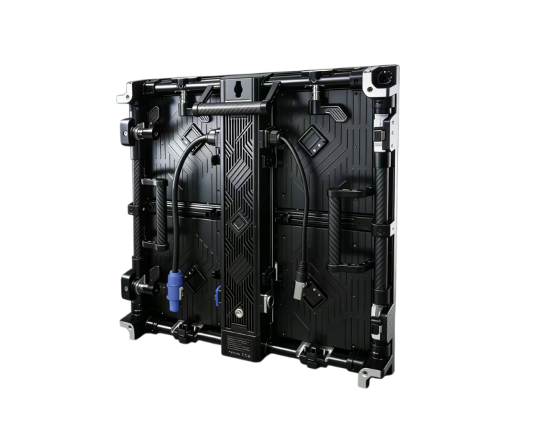
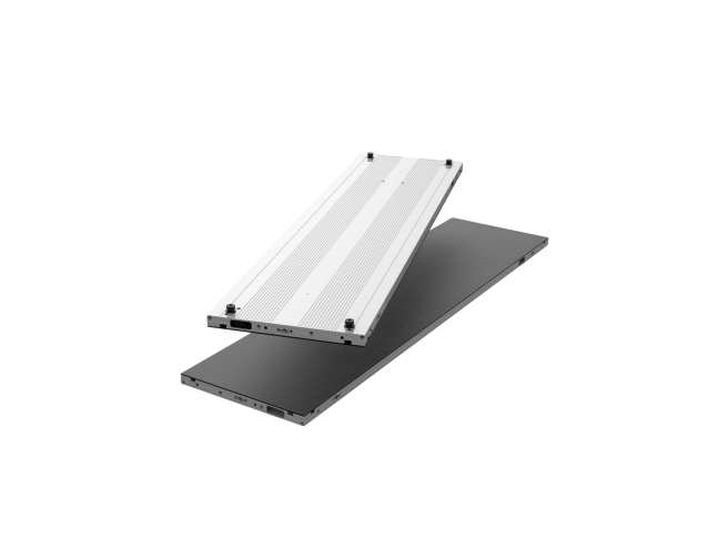
Sostron Carbon Pro
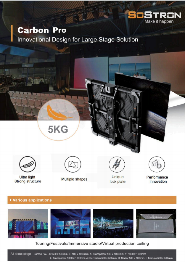
Sostron Carbon Pro is the benchmark for studio, touring, and XR virtual production environments requiring camera-ready display performance. The Carbon Pro achieves a 3,840–7,680 Hz refresh rate range using high-end driver ICs (MBI-tier), which eliminates scan line artifacts across all professional camera shutter configurations from 1/50s to 1/1000s. Its PWM architecture maintains this performance at low brightness levels—a non-negotiable requirement for studio environments where ambient light control and camera exposure balance dictate display output levels as low as 20% rated brightness.
The Carbon Pro’s carbon fiber panel construction serves a dual engineering function that standard aluminum cabinets cannot match.
Thermal Stability
First, the near-zero thermal expansion coefficient of carbon fiber maintains panel flatness—and therefore seamless visual uniformity—under the sustained heat output of professional studio lighting rigs, where die-cast aluminum cabinets can exhibit thermal gap expansion visible as luminance seams on camera.
Lightweight Structure
Second, at 5kg per panel (approximately 40% lighter than equivalent aluminum), the Carbon Pro allows larger hanging arrays in venues with structural weight constraints, directly expanding the usable backdrop dimensions for studio designers.
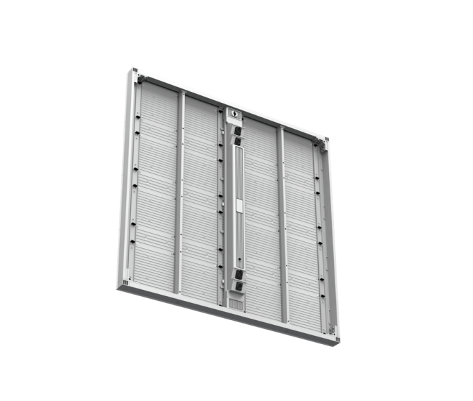
Sostron Hima Series XR LED Display
For virtual production stages, XR studios, and broadcast environments requiring extended-reality integration, the Sostron Hima Series XR LED Display delivers the full technical package for real-time rendering workflows.
With full-black LED technology for maximum native contrast, genlock-compatible processing support, and a modular architecture that accommodates right-angle cube configurations, floor panels, and curved volumes—the Hima Series enables production teams to build any spatial geometry required by modern LED volume shooting methodology.
Real-World Validation: Virtual Production Studio Deployment
The adoption of XR LED technology for broadcast and virtual production has accelerated dramatically.
When Disney’s The Mandalorian production team deployed large-scale LED volumes at Manhattan Beach Studios, the key technical requirements were identical to those governing any broadcast studio display:
- Refresh rates fast enough for cinema cameras
- Color calibration to match the on-set lighting reference
- Zero tolerance for on-camera artifacts
The production validated that fine pitch LED—properly specified—could replace the entire green screen and location shooting pipeline for complex scene work.
Sostron’s deployment record in virtual studio and broadcast environments reflects this convergence of cinema and broadcast LED requirements. The company has supplied LED products to virtual studios internationally and delivered broadcast-facing rental configurations in European markets, supported by a 14-year manufacturing history at its 15,000m² Shenzhen facility.
For system integrators specifying studio installations requiring documented technical support infrastructure and global spare-parts availability, this operational depth translates directly into reduced project risk.
Broadcast Color Science—Why Rec.709 Calibration Is Non-Negotiable for Your TV Studio Display
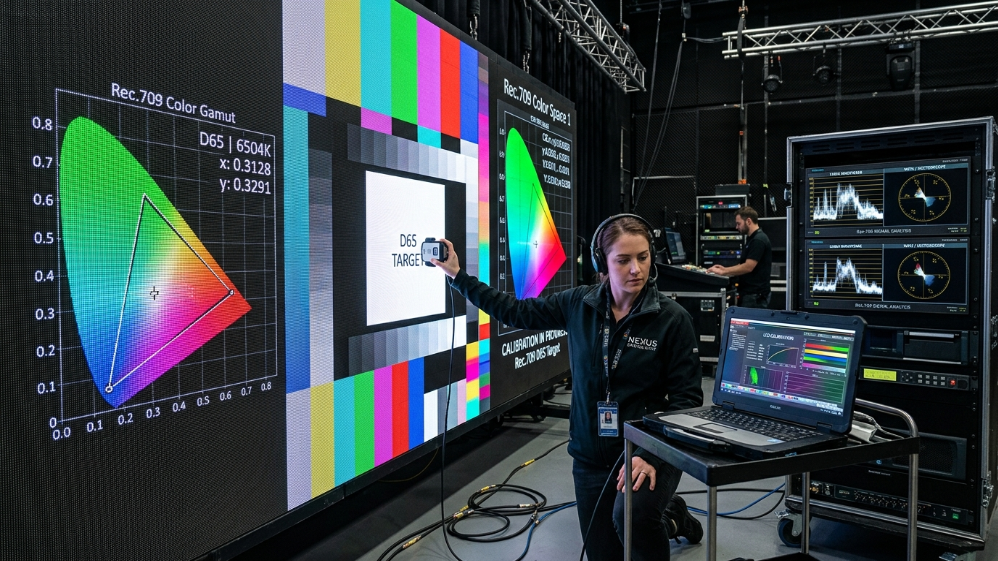
Color is where the gap between “looks good on the show floor” and “performs correctly on air” becomes most expensive.
A broadcaster screen can have the right pixel pitch and a 7,680 Hz refresh rate and still deliver unacceptable output if its color engine is not calibrated to the ITU broadcast delivery chain.
D65 White Point and Broadcast Accuracy
Studio lighting designers build their rigs to a D65 white point reference—6,500 Kelvin color temperature, the standard baseline for Rec.709 HD broadcast and Rec.2020 UHD/HDR delivery.
If the LED wall‘s native white point is calibrated to 7,500K or 8,000K (which is common for displays optimized for retail brightness impact), every white region on that screen will read as a cold blue cast on camera.
The talent’s skin tones, color-corrected to D65 in post, will be out of balance with the background display.
Grading that inconsistency in a live broadcast environment is not possible. It must be resolved at the hardware specification stage.
Factory Calibration Requirements
Factory calibration to Rec.709 means each panel has been individually measured and adjusted so that:
- Primary color coordinates map to the ITU-R BT.709 gamut boundary
- White point lands on D65
- Delta E ≤1.0 across the full brightness range
A Delta E below 1.0 is imperceptible to the human eye and, critically, imperceptible to a calibrated broadcast camera.
This is not a theoretical standard. It is a deliverable that any broadcast-grade manufacturer should provide as a factory calibration certificate per panel, tied to individual serial numbers.
How Low-Reflection Anti-Glare Masks Protect Color Integrity Under Studio Lighting
A calibrated color engine can be partially defeated by the wrong mask material.
Studio environments deploy high-output tungsten, LED, or HMI fixtures at oblique angles to illuminate talent. When those fixtures strike a high-gloss LED mask surface, they produce specular reflections—localized bright hotspots that appear on camera as overexposed regions on the background display.
The effect is not subtle. It reads as blown-out white patches on the finished broadcast image, regardless of what content the display is actually showing.
Anti-Reflective Specification Requirements
Matte black mask surfaces with a measured reflectance value ≤5% absorb the majority of incident studio light rather than returning it toward the camera lens.
This is not an aesthetic preference—it is a measurable optical specification with a direct impact on broadcast image quality.
When specifying a fine pitch LED for studio use, require the mask reflectance value in writing alongside refresh rate and color calibration data.
A vendor who cannot provide this number is not operating at broadcast specification depth.
Broadcaster Screen Reliability—The Engineering Case for Dual Redundancy
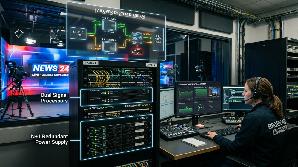
For a DOOH installation or a corporate lobby display, a component failure means a dark screen until the maintenance team arrives.
For a live broadcaster screen during a network news program or a championship sports broadcast, the same event means an immediate, public, on-air failure.
These are categorically different risk profiles, and the engineering response must be proportional.
N+1 Hot-Swap Redundancy
N+1 hot-swap redundancy is the standard architecture for broadcast-critical LED installations.
It means every power supply unit and every signal processor in the system has an active backup that is live, synchronized, and capable of assuming full load within a single frame—or zero perceptible frames at the viewer level—if the primary component fails.
Broadcast LED Redundancy Architecture: Component-Level Requirements
| System Layer | Single-Point Failure Risk | Broadcast-Grade Redundancy Solution | Failover Time |
|---|---|---|---|
| Power Supply (PSU) | Display section goes dark | N+1 hot-swap PSU per cabinet; load-sharing under normal operation | <1 frame |
| Signal Processor | Full wall loses signal | Dual independent processing paths; primary + standby sync’d in real time | 0 perceptible frames |
| Signal Cable Path | Single point cut = full signal loss | Dual-fiber or dual-copper ring topology; auto-reroute on break | <1 frame |
| Receiving Card | Panel section loses signal | Dual receiving card per cabinet; active redundancy | 0 perceptible frames |
| Content Source | Source failure = black wall | HDMI/SDI backup input with auto-switchover | Typically <2s |
Remote Monitoring and Predictive Maintenance
Remote monitoring completes the reliability picture.
Broadcast-grade LED deployments should include real-time panel health telemetry:
- Temperature monitoring
- Voltage monitoring
- Receiving card status monitoring
Predictive thermal alerts that flag a PSU approaching failure threshold before it fails are the difference between a scheduled maintenance window and an emergency during a live event.
5 Questions Broadcast Engineers Always Ask Before Specifying a Studio LED Wall
Q1: Our studio cameras shoot at both 25fps and 50fps. Will the same display work for both frame rates without re-configuration?
Yes—but only if the display’s PWM refresh rate is sufficiently high.
A 3,840 Hz system clears both 25fps and 50fps without artifact.
The processor’s Genlock input must accept both PAL-standard black burst (25/50Hz reference) and HD tri-level sync.
Confirm this dual-standard input capability before finalizing the specification.
Q2: We run ARRI Alexa cameras on our studio floor with variable shutter angles. What is the safe operating window?
At 3,840 Hz PWM and with Genlock active, shutter angles from 90° to 270° at standard frame rates (24/25/30/50/60fps) are generally artifact-free.
At 7,680 Hz, the safe window extends to 360° shutter at any standard frame rate.
For high-frame-rate shooting above 60fps—common in sports production—specify 7,680 Hz PWM as a hard requirement, not a preference.
Q3: How often does the display need re-calibration in a live studio environment, and what does that process involve?
Factory calibration to Rec.709 is stable for approximately 12–18 months under typical studio operating conditions (600–800 hours annual use at controlled brightness).
Field re-calibration uses colorimeter-based measurement against the original factory LUT reference and typically requires 2–4 hours for a standard studio backdrop.
Specify that the manufacturer provides the original calibration data file with the installation—it is the baseline reference that makes accurate field re-calibration possible.
Q4: Our studio uses a motorized camera tracking system for XR virtual production. What display specs affect tracking performance?
Camera tracking systems in XR environments require the display’s content engine to synchronize with the tracking data stream and rendering engine—typically Unreal Engine or Disguise.
Key Display-Side Requirements
- Genlock input at the processor level
- Support for 3D LUT output profiles
- Low signal latency through the processing chain (target <1 frame end-to-end)
Confirm these with your rendering engine vendor before hardware procurement.
Q5: We are comparing fine pitch LED against a high-end LCD video wall for our news studio. What is the honest TCO comparison?
LCD video walls have visible bezels—physical seams between panels typically 1.8mm to 3.5mm wide—that read on camera as a grid pattern across the background image.
Fine pitch LED is physically seamless.
For broadcast use, this difference is binary:
- LCD bezels are visible on air
- LED is not
On the maintenance side, LCD backlights degrade non-uniformly over 3–5 years, requiring matched panel replacement to maintain color consistency.
LED modules degrade more slowly and can be individually replaced without affecting adjacent panels.
At a 7-year TCO horizon including maintenance, re-calibration, and operational downtime costs, fine pitch LED consistently outperforms LCD in camera-facing broadcast applications.
Expert Verdict
The broadcast display market does not punish over-specification—it punishes under-specification.
A P1.5 COB panel with 3,840 Hz PWM, factory Rec.709 calibration, and N+1 redundancy will perform correctly every time.
A P2.5 SMD panel with 1,920 Hz and no redundancy will perform correctly most of the time.
In a broadcast environment, “most of the time” is an unacceptable specification.
Final Procurement Checklist
- Specify the Genlock input.
- Require the calibration certificate.
- Demand the failover time in frames—not in seconds.
If a vendor cannot answer those three questions in writing before you issue a PO, they are not a broadcast partner.
They are a display vendor.
For system integrators evaluating camera-ready LED for studio or virtual production deployment, the Sostron Carbon Pro (for touring and permanent studio installs) and Hima Series XR (for LED volume and XR stage builds) deliver the full technical stack—high-PWM refresh, broadcast color calibration, redundant architecture, and COB-adjacent surface treatment—at a specification depth that justifies the investment on first-air-date performance alone.
Request your technical datasheet and factory calibration sample at [Contact Page].
References:
SMPTE Standards – Broadcast Engineering Reference
EBU Technical Standards for Television Production